| Author |
Message |
Totto91
Joined: 04/19/2023
Posts: 8
Karma: +1 / -0 
1996 BMW 5 Series
Free account, no CAN development support
|
 21-04-2023, 23:38 Subject: LED taillights 21-04-2023, 23:38 Subject: LED taillights |
Quote |
|
Hello everyone, and thank you for the welcome.
I have been looking for a way to repair my defective CAN bus controller in my LED taillights for some time now.
I'm not very familiar with this topic, and I hope I'm in the right place.
I've already tried several forums, and this one was recommended to me.
My problem:
I own a BMW E39 528i, and some years ago I bought taillights that cost me quite a bit of money.
Link to my taillights:
https://crw-autoteile.de/led-rueckleuchten-set-satz-5er-bmw-e39-limousine-rot-smoke-schwarz-bj-95-00
On the website, in the second image, you can see what is called the CAN bus controller.
One of the taillights had a faulty CAN bus controller.
When I tried to take a closer look at the controller, I only saw various components embedded in resin.
I tried to remove the resin, but I ended up damaging the part even more.
Following this, I disassembled the device that was still fully functional and discovered that it contains four ceramic resistors, one capacitor, and one diode.
Okay, so I thought I'd measure it with the multimeter to see what ohm values I'm getting.
On a resistor, you'll see the markings "5W 400Ω".
However, when I measure it, I only get a reading of 99.9 or 101 for all four resistors.
For the diode, I have a value of 100.
Did I do something wrong when taking the measurement, or is it not possible to measure it accurately while it's in a soldered state?
since all 4 resistors are soldered in parallel?
I would appreciate some help because I would like to get these taillights working again.
I thank you in advance.
Sure, here is the translation of the text from German to English:
"MFG" stands for "Mit freundlichen Grüßen," which translates to "Sincerely" or "Best regards" in English. It is a common way to end a formal letter or email.
Translated on 10-07-2026, 9:56.
|
|
| Back to top |
Profile PM Garage |
 |
CAN-Diagnose
Administrator


Joined: 06/07/2011
Posts: 575
Karma: +29 / -0
Location: Ländle
|
| 22-04-2023, 16:17 Subject: LED taillights |
Quote |
|
Hello,
If you connect four resistors of 400 ohms in parallel, the resulting resistance will be 100 ohms.
Even though lighting fixtures often have "CAN" or "CAN Bus" printed on them, it is almost always the case that these systems are not actually installed.
Ehrlich gesagt ist mir schleierhaft, warum diese Anbieter immer so bekloppt daher reden. Wenn ich in meiner Küche einen Kühlschrank habe und ein Leuchtmittel für die Deckenlampe suche, schreibe ich ja auch nicht "Kühlschrank" dazu... 
It has nothing to do with LEDs or the CAN bus.
In more modern vehicles, there is an onboard computer that controls various functions, including checking the lights or adjusting their brightness.
For incandescent bulbs (that are not lit), a voltage is briefly applied to check if any current flows. If the bulb is already lit, the current is naturally checked anyway. If there is current flowing, the filament is okay. If no current flows, the bulb has burned out, and an appropriate message can be displayed on the dashboard.
When LEDs are installed instead of incandescent light bulbs, there are two problems:
- The voltage is too low and is being recognized as a "defective light bulb."
- Depending on the testing method, the LEDs may appear to be glowing or flickering even when they are supposedly "off."
The high-wattage resistors and the capacitor are there to simulate a filament that hasn't burned out. However, they are completely unnecessary.
Sometimes, in Audi/VW/Seat/Skoda vehicles, the on-board control unit supports both incandescent bulbs and LEDs (depending on the vehicle's equipment). Using VCDS, you can reprogram the control unit to switch to a different type of light source, allowing it to function correctly even without any modifications.
If the LED in your taillight is not working, there are three possible causes:
- The body control module indicates a defective light bulb. Troubleshooting should focus on the resistors and capacitors in this circuit. Electrically, there isn't much that can break; usually, it's a loose connection.
- The LED itself is defective. While there are often loose connections, unfortunately, these cannot be repaired within the LED.
- Another issue, just for testing: connect the original light.
My suggestion would be to use LED bulbs with a standard lamp holder, along with a workaround so that the built-in vehicle control unit doesn't complain about it, or ideally, proper coding of the vehicle control unit for LED operation.
Best regards, Rainer.
Last edited on 22-04-2023, 16:23, edited 3 times in total.
|
|
| Back to top |
Profile PM WWW |
|
Totto91
Joined: 04/19/2023
Posts: 8
Karma: +1 / -0
1996 BMW 5 Series
Free account, no CAN development support
|
| 23-04-2023, 9:29 Subject: LED taillights |
Quote |
|
Thank you for the quick response.
It is not possible to replace the rear lights.
Currently, I have the original taillights installed, and they are working perfectly fine.
Back then, I noticed that the on-board computer displayed a message indicating that the right rear light was defective.
When I tried to fix it by replacing the brake light or turn signal bulb, the problem was still there.
Then I investigated further and saw that the LED lights were blinking and flickering.
After that, I searched for the error and saw that the LED CAN bus controller had exploded.
When I removed the controller, I noticed that the capacitor on the top of the housing had burst.
I tried to repair it, but it was impossible because it was encased in resin.
So, I ended up scrapping the entire controller.
As you already mentioned, the controller is only a simulation for the 16 LEDs and serves to make the system appear like it's consuming power.
The LEDs are working properly.
Okay, so if I buy four ceramic resistors at 390 ohms each, one diode with a value of 100, and one capacitor with a capacitance of 100 µF, could I build the system myself?
Is there anything I should be aware of or improve regarding this?
Thank you in advance for your help.
Sure, here is the translation of the text from German to English:
"MFG" stands for "Mit freundlichen Grüßen," which translates to "Sincerely" or "Best regards" in English. It is a common way to end a formal letter or email.
Translated on 10-07-2026, 10:06.
|
|
| Back to top |
Profile PM Garage |
|
Totto91
Joined: 04/19/2023
Posts: 8
Karma: +1 / -0
1996 BMW 5 Series
Free account, no CAN development support
|
|
| Back to top |
Profile PM Garage |
|
CAN-Diagnose
Administrator
Joined: 06/07/2011
Posts: 575
Karma: +29 / -0
Location: Ländle
|
| 23-04-2023, 10:49 Subject: LED taillights |
Quote |
|
Check if there are any resistors (R1 - R4) on the long circuit board acting as current-limiting resistors before the LEDs. If so, you can try applying power with a 9V battery and see if it lights up. Test both polarities of the 9V battery, especially if the polarity is not indicated on the connector or circuit board.
With a 9V power supply, the LEDs should at least light up faintly; if they do, you know that the basic setup is working. Are the diodes okay?
|
|
| Back to top |
Profile PM WWW |
|
Totto91
Joined: 04/19/2023
Posts: 8
Karma: +1 / -0
1996 BMW 5 Series
Free account, no CAN development support
CAN-Diagnose likes this. |
| 23-04-2023, 12:09 Subject: LED taillights |
Quote |
|
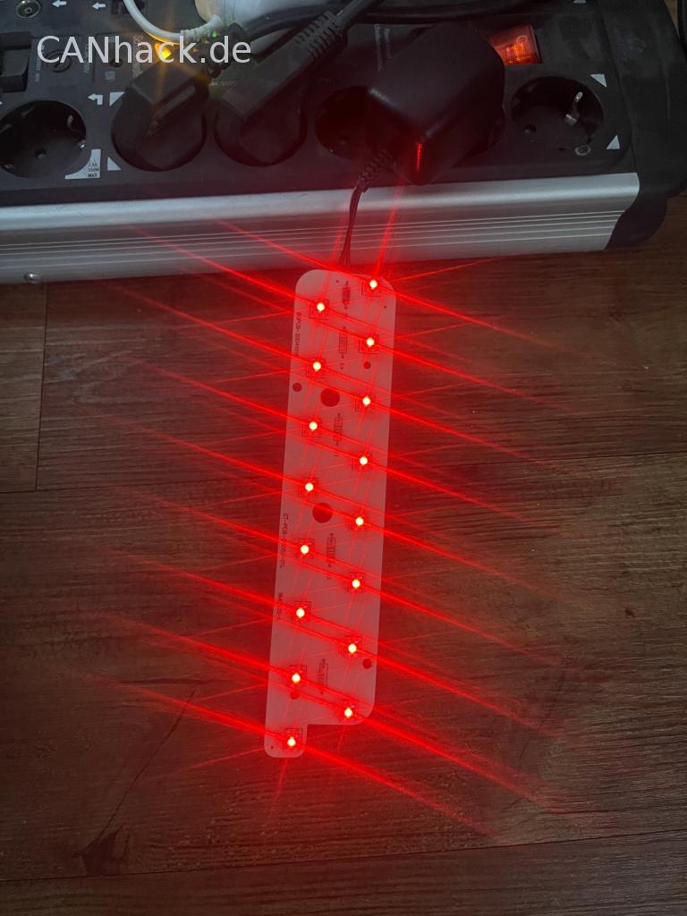
I tested it. I didn't have a 9-volt battery on hand, but I did have a transformer with 5 volts and 180mA.
It was enough to run it.
| Description: |
|
| File size: |
2.17 MB |
| Viewed: |
287 times |
|
Translated on 10-07-2026, 10:11.
|
|
| Back to top |
Profile PM Garage |
|
Totto91
Joined: 04/19/2023
Posts: 8
Karma: +1 / -0
1996 BMW 5 Series
Free account, no CAN development support
|
| 25-04-2023, 11:42 Subject: LED taillights |
Quote |
|
What can I do now?
Is that enough if I use four 390-ohm resistors?
A diode, 100 microamperes.
A 100 µF capacitor.
Or should I make some changes to improve its quality?
Sure, here is the translation of the text from German to English:
"MFG" stands for "Mit freundlichen Grüßen," which translates to "Sincerely" or "Best regards" in English. It is a common way to end a formal letter or email.
Translated on 10-07-2026, 10:12.
|
|
| Back to top |
Profile PM Garage |
|
CAN-Diagnose
Administrator
Joined: 06/07/2011
Posts: 575
Karma: +29 / -0
Location: Ländle
|
| 27-04-2023, 10:54 Subject: LED taillights |
Quote |
|
Totto91 wrote: | What can I do now?
Is that enough if I use four 390-ohm resistors?
A diode, 100 microamperes.
A 100 µF capacitor.
Or should I make some changes to improve its quality?
Best regards | .
Diode: keine Ahnung was Du damit sagen willst, als Maximalstrom sehr klein. Take a 1N4007.
 |
|
| Back to top |
Profile PM WWW |
|
Totto91
Joined: 04/19/2023
Posts: 8
Karma: +1 / -0
1996 BMW 5 Series
Free account, no CAN development support
|
| 29-04-2023, 11:13 Subject: LED taillights |
Quote |
|
|
Translated on 10-07-2026, 10:14.
|
|
| Back to top |
Profile PM Garage |
|
CAN-Diagnose
Administrator
Joined: 06/07/2011
Posts: 575
Karma: +29 / -0
Location: Ländle
|
| 30-04-2023, 11:29 Subject: LED taillights |
Quote |
|
Hello.
The components are not critical. When it comes to the electrolytic capacitor, you absolutely must pay attention to the correct polarity; otherwise, it might explode and fly off.
It's actually quite unlikely that they would break, so I would definitely check the wiring, circuit board, solder joints, and connectors.
Und ein Diagnosegerät wo Du das Bordnetzsteuergerät checken kannst wäre hilfreich. Eventuell ist es notwendig vor Prüfungen Deiner LED immer eine Rückleuchte mit funktionierenden Lampen anzuschliessen und dann Zündung an/aus usw. Weil wenn einmal "Kurzschluss erkannt", wird auch kein Strom mehr geschickt. 
Best regards, Rainer.
Last edited on 30-04-2023, 11:31, edited 1 time in total.
|
|
| Back to top |
Profile PM WWW |
|
Totto91
Joined: 04/19/2023
Posts: 8
Karma: +1 / -0
1996 BMW 5 Series
Free account, no CAN development support
|
| 01-05-2023, 21:09 Subject: LED taillights |
Quote |
|
Both circuit boards on the left and right sides of the taillight are functioning properly.
My car's right-hand CAN bus control unit burned out back then.
I also connected the left wire to the right taillight, and it worked without any problems.
When I examined it closely back then, I noticed that the capacitor had burst.
Replacing only the capacitors was not possible because the entire control unit is encased in resin.
So, I'm left with no other option but to recreate the control unit myself.
You don't get a replacement for it either.
To get back to my question...
Can I use the component that I showed you, or do I need to get different ones?
I would like to get the taillights working again.
Sure, here is the translation of the text from German to English:
"MFG" stands for "Mit freundlichen Grüßen," which translates to "Sincerely" or "Best regards" in English. It is a common way to end a formal letter or email.
Translated on 10-07-2026, 10:17.
|
|
| Back to top |
Profile PM Garage |
|
CAN-Diagnose
Administrator
Joined: 06/07/2011
Posts: 575
Karma: +29 / -0
Location: Ländle
|
| 02-05-2023, 23:51 Subject: LED taillights |
Quote |
|
Hello,
That should work; just make sure to pay attention to the correct polarity when installing the capacitor!
Best regards, Rainer.
|
|
| Back to top |
Profile PM WWW |
|
Totto91
Joined: 04/19/2023
Posts: 8
Karma: +1 / -0
1996 BMW 5 Series
Free account, no CAN development support
|
| 11-05-2023, 8:00 Subject: LED taillights |
Quote |
|
Okay, I've ordered all the parts and also soldered together the mentioned CAN bus module. The LEDs in the car are working again without any problems. However, the onboard computer is displaying a message that the bulbs are defective.
Apparently, the load resistance is still too low for the current consumption.
I've been spending the last two days trying to figure out what the original device's load resistance is and how many watts/amps it consumes.
I'm going to take a chance and hope I'm right about this.
Two wires connect to the original rear light assembly. Each wire is powered by 12 volts. The power supply for the original bulbs is 5 watts, which corresponds to a current consumption of 0.42 amps per bulb.
Calculating the combined current of the two pears results in a value of 0.83A.
Now, about the LED:
The LEDs are arranged in a 4x4 configuration.
This means that 4 LEDs are connected in series, and there are a total of 4 such sets on the circuit board.
When four of them are connected in series, they run together in parallel.
I figured out exactly what kind of LEDs they are.
SuperFlex VIS TLWR8600, RED.
The data:
2.2 volts.
70 mA.
So, I just added up the values of the four consecutive numbers.
0.07 A x 4 = 0.28 A
So, I calculate that 12 volts / 0.28 amps equals 3.36 watts.
Since two bulbs are running and both of their power is being channeled into the LED, I'm adding their wattage together.
5 watts x 2 = 10 watts.
Subsequently, I calculated.
10 Watts minus 3.36 equals 6.64 Watts that still need to be vaporized.
So, I'll continue calculating.
6.64 Watts / 12 Volts = 0.553 Amps.
Now, regarding the resistance:
Resistance R = 12 Volts / 0.552 Amps = 21.699 Ohms.
I have adjusted the resistance to 22 ohms.
I've picked them out.
https://www.reichelt.de/drahtwiderstand-axial-7-w-22-ohm-10--7w-axial-22-p110655.html?&trstct=pos_2&nbc=1
Here is my question.
Do I need just one resistor, or four resistors, since there are four LEDs in series, and another four LEDs connected in parallel to them?
I'm not quite sure I understand anymore.
The resistors I bought are 390 ohms, while the originally installed ones were 400 ohms.
Since I connected my four 390-ohm resistors in parallel, the value is divided by 4.
However, I also need to add something.
I supplied the circuit board where the LEDs are mounted with 12 volts using a transformer and measured the voltage after the resistors. The reading was 7.32 volts.
Before the first LED.
After the first LED: 5.48 volts / 3.64 volts / 1.82 volts.
And I have the same values for all four rows.
I'm not an expert in this area, and I'm trying to contribute as much as possible.
But I just can't seem to figure out this system...
Please provide the text you would like me to translate from German to English. I'm ready when you are.
Sure, here is the translation of the text from German to English:
"MFG" stands for "Mit freundlichen Grüßen," which translates to "Sincerely" or "Best regards" in English. It is a common way to end a formal letter or email.
Translated on 10-07-2026, 10:24.
|
|
| Back to top |
Profile PM Garage |
|
|


 Bookmarks
 Garage
 FAQ, Legal Notice & Privacy
 RSS Feed
 Register
 Login
Login