| Author |
Message |
wernernue
Joined: 03/02/2016
Posts: 27
Karma: +10 / -0 
Location: Nürnberg
Premium Support
CAN-Diagnose likes this. |
 11-05-2016, 0:23 Subject: Motor simulation of an AZQ motor using Polo engine control units 11-05-2016, 0:23 Subject: Motor simulation of an AZQ motor using Polo engine control units |
Quote |
|
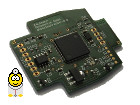
Now that my virtual Polo is pretty much finished, I wanted to show it off. The system consists of the body control module, engine control module, instrument cluster, and comfort control module.
To bring the entire system to life, the signals from the crankshaft and camshaft sensors, as well as the speed pulses, are generated by 2 Arduino microprocessors, which then control all actuators. These actuators are implemented using LEDs or incandescent lamps (e.g., for the lambda sensor heaters), or with real components, such as the throttle valve. The sensors are either equipped with adjustment knobs or, in some cases, are built with actual components like a gas pedal or throttle valve.
The "speed control" of the Arduino is achieved by integrating the control pulses for the fuel injectors and feeding the control voltage to an analog input of the Arduino microcontroller. This control method means that the control of the fuel injectors is crucial for the performance of the engine. The cruise control system, which consists of 5 individual switches, is fully functional and can maintain the set speed.
The "virtual 5-speed manual transmission" converts the speed signal into different ratios relative to the engine speed. During the shifting process, the new engine speed value is calculated based on the speed signal and the new gear ratio, and then set as the actual value.
This creates almost real-world conditions on the drive-related CAN bus.
The structure on the "board" allows for individual sensor values to be modified arbitrarily (e.g., the oil temperature from sensor G266, which is also emulated by an Arduino microcontroller). This, combined with the clear visualization of individual bytes, makes it easy to identify the corresponding CAN message.
I will then present the results in a file here.
As a conclusion, I can already say that it provided a great deal of information about how things work, as well as about false or missing signals.
| Description: |
|
| File size: |
1.17 MB |
| Viewed: |
3684 times |

|
| Description: |
|
| File size: |
4.21 MB |
| Viewed: |
7925 times |

|
| Description: |
|

Download |
| File name: |
MKV Polo CAN-BUS data.xls |
| File size: |
183.5 KB |
| Downloaded: |
947 times |
Last edited on 11-05-2016, 0:30, edited 1 time in total.
|
|
| Back to top |
Profile PM |
 |
CAN-Diagnose
Administrator

Joined: 06/07/2011
Posts: 573
Karma: +29 / -0
Location: Ländle
|
| 11-05-2016, 9:15 Subject: Motor simulation of an AZQ motor using Polo engine control units |
Quote |
|
Cool project! Will this be some kind of "display board" for training purposes?
Best regards, Rainer.
|
|
| Back to top |
Profile PM WWW |
|
wernernue
Joined: 03/02/2016
Posts: 27
Karma: +10 / -0
Location: Nürnberg
Premium Support
|
| 11-05-2016, 15:16 Subject: Motor simulation of an AZQ motor using Polo engine control units |
Quote |
|
Hello Rainer,
The idea came about from having a spare comfort control unit after I installed a remote central locking system in my Polo. The need for a CAN gateway quickly became apparent, and a suitable body control module was found. Then, everything was connected with temporary wiring, an OBD socket was salvaged from a scrapyard, and I was able to access it using VCDS. After reconfiguring the gateway, the error messages for the missing control units disappeared, except for the instrument cluster and the engine control unit.
It's kind of logical, because you can't have a car without a speedometer and engine, so those two control units were still needed. I found them along with a key and the corresponding transponder. Then, I added an ignition switch with the reading coil, and the CAN bus errors disappeared. To understand the CAN signals measured with the oscilloscope, a CAN interface was also needed.
And then the idea came about to simulate impulses for the MSG, and since my colleague is very familiar with Arduinos, I decided to use them as well.
The initial signal patterns were still implausible for the control unit, but after some research, the signal shape turned out to be correct. And the recurring error messages caused by missing sensors were gradually resolved by connecting potentiometers and other components. For a long time, intermittent misfires were a problem, caused by signal instability (jitter), which was likely due to a defect in an analog input. This defect eventually resolved itself.
I will be posting some interesting oscillograms here, and I will also describe some of the applications of Arduinos. For suggestions, I am happy to be 
I hadn't originally intended for it to be a display, but my colleagues from our vehicle fleet department (I work in IT) have already expressed interest in a demonstration.
Best regards from Nuremberg,
Werner.
Last edited on 11-05-2016, 15:18, edited 1 time in total.
|
|
| Back to top |
Profile PM |
|
CAN-Diagnose
Administrator
Joined: 06/07/2011
Posts: 573
Karma: +29 / -0
Location: Ländle
|
| 11-05-2016, 15:40 Subject: Motor simulation of an AZQ motor using Polo engine control units |
Quote |
|
Ok  |
|
| Back to top |
Profile PM WWW |
|
postmann
CAN-Profi

Joined: 05/23/2013
Posts: 142
Karma: +63 / -0
CAN Support
|
| 11-05-2016, 21:47 Subject: Motor simulation of an AZQ motor using Polo engine control units |
Quote |
|
Wow, great job . |
|
| Back to top |
Profile PM |
|
wernernue
Joined: 03/02/2016
Posts: 27
Karma: +10 / -0
Location: Nürnberg
Premium Support
|
| 12-05-2016, 0:44 Subject: Motor simulation of an AZQ motor using Polo engine control units |
Quote |
|
Thank you .
Okay, so I'll briefly describe how the cruise control system works here.
You need a 2-pole switch that latches (normally closed contact S1).
a button (normally open, S2) for the "Cancel" function.
a button (normally closed contact S3) for the reset or (+) function.
a button (normally closed contact S4) for the set/minus (-) button.
a diode, e.g., 1N4148.
The common terminal of the four switches is connected to +12V when switch S1 is turned on. The white wire is connected to pin 3 of connector XP3 on the body control module (BCM) and runs through the wiring harness in the front bulkhead, where it then connects to the engine control module (ECM). For the AZQ engine, the connection pin is pin 28 on the ECM. The connection is made via the white connector on the front panel, using pin 10. The cable in the engine compartment leading to the control module (MSG) is usually already pre-installed.
In measurement block 9 of the vehicle's control unit, you can see the switches. If it says "not installed" there, the control unit is not suitable.
The GRA (Gas Recirculation) needs to be enabled in the engine control unit. This exceeds the login code 11463.
In measurement block 66, you will find the switches again. Specifically, in the 4th one. The least significant bit represents the state of switch 1, the second bit from the right represents switch 2, the third bit from the right represents the "Set" button, and the fourth bit from the right represents the "Reset" button.
The second byte contains the switch status of the two brake switches and the clutch switch, which must be 0 for normal operation (brake and clutch not engaged).
The fourth bit is always 1 when the GRA has been enabled via the login code.
With these 4 switches, you can eliminate the need for a steering column lever and avoid the issue of airbag deployment. The only remaining challenge is running the cable to the connector located on the front panel.
| Description: |
|
| File size: |
8.45 KB |
| Viewed: |
3737 times |

|
|
|
| Back to top |
Profile PM |
|
wernernue
Joined: 03/02/2016
Posts: 27
Karma: +10 / -0
Location: Nürnberg
Premium Support
stadelschrauber likes this. |
| 17-05-2016, 12:19 Subject: Cruise control: Error messages and CAN |
Quote |
|
Here's some more information about error message 17977 - Speed control switch (GRA/E45).
P1569 - 35-00 - implausible signal.
In cases of persistent errors (i.e., not sporadic), the cause of the error is a missing or faulty wiring connection between the body control module and the engine control module.
If the white cable was pulled to the connector in the bulkhead, then the subsequent cable leading to the MSG is likely missing. The connection pin on the MSG is different; on the AZQ, it is pin 28.
If the error message appears intermittently, is it more likely due to a wiring issue or the switch itself?
The information from the vehicle's body control module is contained in two CAN addresses, namely 388 and 38A. These can be seen on the vehicle's body control module, even if the CAN connection is disconnected.
Every other time. Byte (BB) represents the information contained within the switches.
388 3Byte AA BB CC
38A 4Byte AA BB CC DD
BB: 01 Cruise control ON.
BB: 02 Cruise control OFF.
BB: 03 Cruise control CANCEL.
BB: 05 SET (down)
BB: 09 RESET (+)
???????x OFF=0 ON=1
I cannot translate this because it contains only question marks and the letter "x". It is not a complete sentence or phrase. CANCEL=1 Normal=0
I cannot translate this because it appears to be a string of random characters. It doesn't form a coherent sentence or phrase in German. SET=1
I cannot translate this as it is not a complete sentence or phrase. It appears to be a string of characters with question marks and "x". RESET=1
|
|
| Back to top |
Profile PM |
|
CAN-Diagnose
Administrator
Joined: 06/07/2011
Posts: 573
Karma: +29 / -0
Location: Ländle
|
| 17-05-2016, 13:04 Subject: Motor simulation of an AZQ motor using Polo engine control units |
Quote |
|
Great! Just a tip regarding the error message, based on my own frustrating experience and annoying troubleshooting: In cases like this, also consider a faulty cruise control lever. That was the problem for me (shortly after buying a new lever). I only realized late that the almost new lever itself might be defective. 
The lever positions can be checked in the diagnostic data blocks of the engine control unit or steering column control unit, or by monitoring the specified bits after tapping into the CAN bus.
Best regards, Rainer.
Last edited on 17-05-2016, 13:05, edited 2 times in total.
|
|
| Back to top |
Profile PM WWW |
|
wernernue
Joined: 03/02/2016
Posts: 27
Karma: +10 / -0
Location: Nürnberg
Premium Support
|
| 17-05-2016, 13:25 Subject: Signals from crankshaft sensor G28 and camshaft sensor G40 |
Quote |
|
The image shows the signals from the crankshaft sensor (G28) and the camshaft sensor (G40). These signals are generated by the Arduino DUE. The temporal sequence of the two signals can be seen in a measurement block within the engine control unit. Flank L > H and H > L on tooth 89 and tooth 29, respectively, counted from the "tooth gap."
The period of the "tooth impulses" is adjusted via an analog input.
At "high speeds," even an Arduino with a 16MHz clock frequency reaches its limits, because the execution time of the loop (the part of the Arduino program that is repeatedly executed in a loop) already takes up a noticeable portion of the period of a single "pulse."
In my setup, I used an Arduino DUE, which is significantly more powerful than the UNO.
In addition, there were issues with the program's setup. Different program conditions result in varying cycle durations, which then manifest as jitter in the signal. The engine control unit may recognize this as a misfire and then disable the affected cylinder. The misfire detection system is based on the detection of a drop in engine speed during the power stroke of the respective cylinder.
Here's the Arduino code snippet with a brief explanation of how it works:
The variable NW (camshaft) continuously cycles through values from 0 to 239. When it reaches 240, it resets to 0 and has then completed exactly one revolution. The crankshaft would have completed exactly 2 revolutions.
The variable "Begin_input" corresponds to 11 and "End_input" corresponds to 21, meaning that during this time, the analog input is read, which affects the period duration of the tooth pulses. Only the data from the first cylinder is used; for the second and third cylinders, the value is read into a dummy variable, which is not used further. This timing occurs before top dead center (TDC) of each cylinder. If it were to occur after TDC, misfires would be detected because the analog input reading requires a certain amount of time, and thus the engine speed would be lower during that phase.
+80 corresponds to the 2nd cylinder, and Code: |
byte NW = 0;
int Signalpause;
int Drehzahlsensor;
int Dummy; //Nur zum Zeitausgleich
int DRZ_soll;
int DRZ_delta;
int DRZ_ist = 700;
byte Begin_input = 11;
byte End_input = 21;
byte NW_Pin=13;
byte KW_Pin=12;
void setup() {
pinMode(13, OUTPUT); //Nockenwellenimpuls
pinMode(12, OUTPUT); //Kurbelwellenimpuls
}
void loop() {
delayMicroseconds(Signalpause);
//A1 einlesen und Soll-Ist Abgleich nur in der Kompriierungsphase
if ( (NW > Begin_input & NW <End_input> Begin_input + 80 & NW <End_input> Begin_input + 160 & NW <End_input> Begin_input + 240 & NW <End_input> Begin_input & NW < Begin_input + 2) {
Drehzahlsensor = analogRead(A1);
} else {
Dummy = analogRead(A1);
}
//Eingangspegel mappen auf ungefähre Drehzahl von 700 bis 5800
DRZ_soll = map(Drehzahlsensor, 80, 870, 700, 5800);
//Verändern der Drehzahl mittels P-Regler
DRZ_delta = DRZ_soll - DRZ_ist;
DRZ_ist = DRZ_ist + DRZ_delta / 10;
//Berechnen der neuen Periodendauer eines Zahnes.
Signalpause = 400000 / DRZ_ist;
}
//Kurbelwellenimpuls HIGH wenn NW ungerade außer bei Zahnlücke
if ( (NW % 2 == 1) & !(NW == 117) & !(NW == 119) & (NW < 237) ) {
digitalWrite(KW_Pin, LOW);
} else {
digitalWrite(KW_Pin, HIGH);
}
//Nockenwellenimpuls HIGH von Zahn 29 bis 89
if ((NW <58> 179)) {
digitalWrite(NW_Pin, LOW);
} else {
digitalWrite(NW_Pin, HIGH);
}
//Zählvariable Nockenwelle wieder auf 0 setzen
if (NW == 240) {
NW = 0;
}
NW = NW + 1;
}
| 60 corresponds to the 3rd. Cylinder.
The comparison of the desired and actual values, as well as the calculation of the signal duration (which represents the duration of a pulse), takes place during this time.
The input signal G28 is connected to pin 12. It goes HIGH when the result of dividing the value of NW by 2 has a remainder of 1, but is not equal to 117, 119, 237, or 239. These 4 values represent the "tooth gaps" corresponding to the missing teeth in the first or second rotation of the crankshaft.
Pin 13 receives the signal from the camshaft sensor (G40). He will be considered "HIGH" when the NW value is greater than 58 and less than 179. (An NW value greater than 58 corresponds to tooth 29, and an NW value less than 179 corresponds to tooth 89).
Pin 13 must be HIGH when NW is greater than 58 and less than 179, which corresponds to teeth 29 and 89 (89 = second crankshaft revolution, tooth 29).
So, that is the heart of this virtual polo. 
Here is the Arduino sketch:
| Description: |
| Motor simulation of an AZQ motor using Polo engine control units |
|
| File size: |
3.92 MB |
| Viewed: |
2394 times |

|
Last edited on 17-05-2016, 21:43, edited 2 times in total.
|
|
| Back to top |
Profile PM |
|
wernernue
Joined: 03/02/2016
Posts: 27
Karma: +10 / -0
Location: Nürnberg
Premium Support
CAN-Diagnose likes this. |
| 19-05-2016, 23:17 Subject: Simulation of the oil level and oil temperature sensor G266 |
Quote |
|
Simulating the oil level and oil temperature sensor G266 using an Arduino UNO.
In addition to the classic oil pressure sensor, another sensor is also installed, primarily to extend the maintenance intervals, which measures the oil level and oil temperature. These two values are transmitted digitally via a single line to the combination instrument. The functionality of this sensor is described in detail in many places on the internet. When experimenting with a combination instrument, you will quickly notice that the signal from sensor G266 is missing, as indicated by the warning tone. A missing signal is indicated by the yellow oil can icon, and depending on the configuration, it is also accompanied by an audible warning.
It is not always possible to reprogram this sensor, so I generate the signal using an Arduino. The waveform is shown in the following image. After a warm-up period to increase the oil temperature inside the sensor, the oil temperature is initially transmitted as a symmetrical square wave (T1). The total time between the two warm-up phases (T2-warm-up time) is representative of the liquid level. The lower the fill level, the longer the cooling phase takes.
If the commented-out section is enabled, a potentiometer can be connected to input pins A0 and A1 of the Arduino. Then, the liquid level and oil temperature can be adjusted.
This replicated sensor is also well-suited for checking the wiring harness in cases of occasional errors, as it allows you to directly connect the Arduino to the instrument cluster. Depending on whether the error still occurs, the wiring or the instrument cluster can be ruled out if a previous replacement of the sensor was unsuccessful.
Just a small note about the warning sound for the classic oil pressure switch. Here, the plausibility is checked by the combination instrument. If the engine is running and the oil pressure switch is not closed, the warning sound is activated, and the red oil can icon illuminates on the instrument cluster. However, it is also checked to ensure that the switch is "open" when the engine is not running. Please send the engine speed data via the CAN bus to the instrument cluster. It will beep when the switch is open, and it will also beep after a few seconds if the engine speed is 0, but the switch remains closed.
Here is the Arduino program code Code: |
int Oelstand;
int Oeltemp;
int T0=16;
int T1=20;
int T2=350;
void setup() {
pinMode(13, OUTPUT);
}
void loop() {
/*
// Den auskommentierten Bereich aktivieren, wenn man die Werte für Füllstand und Öltemperatur variabel verändern möchte
// die Werte können in den MWB am Kombiinstrument angesehen werden.
Oeltemp=analogRead(A0);
T1=map(Oeltemp,0,1023,10,40);
Oelstand=analogRead(A1);
T2=map(Oelstand,0,1023,250,800);
*/
digitalWrite(13,HIGH);
delay(T0);
digitalWrite(13,LOW);
delay(T1);
digitalWrite(13,HIGH);
delay(T1);
digitalWrite(13,LOW);
delay(T2-T1-T1);
}
|
| Description: |
| Motor simulation of an AZQ motor using Polo engine control units |
|
| File size: |
8.28 KB |
| Viewed: |
2282 times |

|
Last edited on 19-05-2016, 23:31, edited 4 times in total.
|
|
| Back to top |
Profile PM |
|
wernernue
Joined: 03/02/2016
Posts: 27
Karma: +10 / -0
Location: Nürnberg
Premium Support
|
| 23-05-2016, 23:21 Subject: Error: Knock sensor signal too high |
Quote |
|
Does anyone know if the error message...
16712 - Knock sensor 1 (G61)
P0328 - 35-00 - Signal too high.
What is a misinterpretation from the engine control unit?
I've already shorted the two connection pins together and grounded them, but I still get the error message that the voltage is too high.
In reality, the signal is too small because it's not a real motor producing sounds, and therefore the connected sensor isn't generating a signal.
My guess is that the error message is displaying the wrong text, meaning it's actually too short, which would make sense.
Thank you in advance.
| Description: |
| Motor simulation of an AZQ motor using Polo engine control units |
|
Download |
| File name: |
Log-N VP 9999-WVWZZZ9NZ3D064797-111530km.txt |
| File size: |
2.17 KB |
| Downloaded: |
629 times |
|
|
| Back to top |
Profile PM |
|
CAN-Diagnose
Administrator
Joined: 06/07/2011
Posts: 573
Karma: +29 / -0
Location: Ländle
|
| 24-05-2016, 9:17 Subject: Motor simulation of an AZQ motor using Polo engine control units |
Quote |
|
Good morning.
Perhaps you miscounted the number of pins on the connector? This kind of thing normally happens to me. 
Best regards, Rainer.
Last edited on 24-05-2016, 9:17, edited 1 time in total.
|
|
| Back to top |
Profile PM WWW |
|
wernernue
Joined: 03/02/2016
Posts: 27
Karma: +10 / -0
Location: Nürnberg
Premium Support
|
| 24-05-2016, 18:56 Subject: Motor simulation of an AZQ motor using Polo engine control units |
Quote |
|
CAN-Diagnose wrote: | Good morning,
Perhaps you miscounted the number of pins on the connector? This kind of thing normally happens to me.
Best regards, Rainer |
Hello Rainer,
I've already opened and checked the connector several times. The two connections go to pins 101 and 109 on the MSG. That's where the signal from the piezoelectric crystal should be present. I haven't connected the shield because my sensor only has 2 connections. In section 26 of the MWB manual, it states 0.1V or 0.08V per cylinder, which seems like a rather low value.
Unfortunately, I can't perform a comparative measurement right now, as I only have diesel vehicles available.
Is Pin 101/109 correct?
Best regards,
Werner. |
|
| Back to top |
Profile PM |
|
CAN-Diagnose
Administrator
Joined: 06/07/2011
Posts: 573
Karma: +29 / -0
Location: Ländle
|
| 26-05-2016, 18:50 Subject: Motor simulation of an AZQ motor using Polo engine control units |
Quote |
|
Could you please tell me what model year and type your simulation is?
|
|
| Back to top |
Profile PM WWW |
|
wernernue
Joined: 03/02/2016
Posts: 27
Karma: +10 / -0
Location: Nürnberg
Premium Support
|
| 27-05-2016, 7:57 Subject: Motor simulation of an AZQ motor using Polo engine control units |
Quote |
|
CAN-Diagnose wrote: | | Could you please tell me what model year and type your simulation is? |
Good morning, Rainer,
Model year 2003.
10/2002
Polo A04 comfo 47 5g
9N11D4
Unfortunately, I don't know any more than that... |
|
| Back to top |
Profile PM |
|
wernernue
Joined: 03/02/2016
Posts: 27
Karma: +10 / -0
Location: Nürnberg
Premium Support
|
| 27-05-2016, 8:05 Subject: Motor simulation of an AZQ motor using Polo engine control units |
Quote |
|
CAN-Diagnose wrote: | | Could you please tell me what model year and type your simulation is? |
I bought the MSG and AI products online.
Last edited on 27-05-2016, 8:09, edited 1 time in total.
|
|
| Back to top |
Profile PM |
|
|

