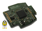
CANhack.de CAN-Interface RKS+CAN
CAN Hardware, CAN Software, CAN Protocols - CAN Bus Forum for Your CAN Bus Project.

Audi A3 8P: Understanding the MID Display System Basics

 
Go to page: 1, 2  Next
New Topic Reply 🔗 🖨 CANhack.de - Index » Vehicle-specific Hardware and Pin Assignments
Author Message
GerdJ
CAN-Profi
CAN-Profi


Joined: 09/08/2014
Posts: 45
Karma: +14 / -0   Thank you, like it!


Premium Support

CAN-Diagnose and carletes45 likes this.
Post28-07-2016, 14:02    Subject: Audi A3 8P: Understanding the MID Display System Basics Quote

Hello,
By meticulously logging and analyzing data, I have deciphered the control mechanism for the central FIS (Flexible Information System) area in the Audi A3 8P and can now display arbitrary text, navigation symbols, and graphics on the screen.
Surprisingly, to my knowledge, only a very few people have managed to do this. Several products that describe the FIS (Fahrzeuginformationssystem) area use the telematics mode for this purpose, but this mode is no longer available in newer tachographs.

Here, you need to use the navigation mode, which means simulating an Audi RNS-E navigation system.

In this post, I will only cover the basics of communication. The detailed approach must be worked out by oneself icon_smile.gif.

Vehicle: Audi A3 8P, manufactured in May 2011, with a speedometer (ending in "TN" - likely a part number), and a large white FIS (Flüssigkristalldisplay / LCD display).
Radio: Audi RNS-E Model 193 (the one with the media button).

Basics:
To display the top two lines, the radio must register with the OSEK ring. The radio then periodically transmits text strings (2x8 characters) to the CAN bus. The FIS (Instrument Cluster) displays this information. There is no confirmation received from the FIS. To send custom text messages, a CAN router (gateway) must be placed between the radio and the CAN bus. This router filters out specific IDs (0x363 + 0x365), while forwarding all other frames.

I solved this using a small circuit board based on an STM32F4 microcontroller.

"For the middle section of the FIS (Instrument Cluster), no OSEK registration is required. It's also possible to access the FIS without using the radio, which can even be easier because you don't have to filter out any frames. For my purposes, I continue to use my module and filter out the relevant messages between the car and the RNS-E (navigation system), and vice versa."

Two IDs are responsible for communication: 0x6C0 and 0x6C1 (0x6C0 originates from the RNS-E system, and 0x6C1 comes from the speedometer).

To figure out the protocol, you only need to log these two IDs on the info-CAN bus and learn how to understand them icon_smile.gif.

Basics:
Upon ignition activation, a transport protocol is established between the speedometer and the RNS-E system, similar to an OBD session. The connection can be initiated and terminated by either participant.
Participant 1 sends a start sequence multiple times to establish the connection. If the other end does not respond within a certain time, the connection attempt is aborted and not retried.

If participant 2 responds to the request, additional frames are sent to the other party and a corresponding response is provided. There are also two types of messages: some that do not require confirmation from the other party, and others that do.

To observe the process, you log both IDs and turn on the ignition. After a short time, the connection will be established and maintained through "Keep-Alive" messages. Then, switch to navigation mode on the RNS-E and activate the compass in the setup. Now you can see what data is being sent from the radio to the instrument cluster to display the direction and the current street name on the FIS (Multi Information Display).

News categories:
0x52 is the command mode.
0x57 is the data mode.
and many more, such as for graphics mode to control individual pixels.

The command mode allows you to define the FIS area that you want to write to (maximum 64x48 pixels). In this mode, you can either define the area, clear it, or fill it with white.

The data mode sends multiple data blocks sequentially to the speedometer, allowing for the display of longer texts, for example.

Frames that begin with the hexadecimal value "1x" must be acknowledged by the receiving device. Frames that begin with the hexadecimal value "2x" do not require acknowledgment.

When analyzing log files, it quickly becomes apparent how confirmations are handled. Specifically, each participant has a sequential counter that is added to frames with the hexadecimal value 1x or 2x, for example, Hex 10, then 11, and so on. When Hex 1F is reached, an overflow occurs, and the counter resets back to Hex 10.

Texts can have multiple formatting styles.
Bold font, thin font, white on black, black on white, XOR to the display, OR to the display, left-aligned and centered alignment.
Furthermore, there is a character set that outputs graphical characters for navigation symbols. However, one must combine several "navi-characters" to create, for example, a left turn arrow, because each individual character is only 6x7 pixels in size.

The RNS-E doesn't utilize all of the capabilities of the FIS (Flexible Instrument System). For example, it's possible to directly address individual pixels in graphics mode, which the RNS-E does not do.

Since we're talking about pixels, the resolution is 64x48 pixels. Each pixel consists of 4 subpixels, which I call "subpixels."
So, essentially, we're dealing with a double exposure. I've now found a way to target those subpixels.
However, one shouldn't expect miracles in terms of speed from the FIS display, as it plays a secondary role in the speedometer (the speedometer does more than people realize!). Therefore, achieving high scores ("Doom") on the FIS is not desirable icon_smile.gif.

After each frame sent to the dashboard, a short pause should be inserted, otherwise frames may be lost, resulting in text being fragmented or, in the worst case, the connection freezing. Don't panic; it's difficult to break anything with the Info-Bus. Simply turning the ignition off and on will usually resolve the issue.

Okay, that's all for now.


Translated on 10-08-2026, 0:14.
Back to top Profile PM
shavenne
CAN-Profi
CAN-Profi


Joined: 04/27/2015
Posts: 37
Karma: +6 / -0   Thank you, like it!
Location: Paderborn

CAN Support

Post28-07-2016, 21:27    Subject: Audi A3 8P: Understanding the MID Display System Basics Quote

Hello 8pa icon_razz.gif.

I even find it interesting as someone who isn't an Audi driver, to see how it works with other brands icon_smile_thumb_up.gif. So far, I've only been able to experiment with the Astra G CID and the (newer) Vectra C CID, and they are quite similar to each other.


Translated on 10-08-2026, 0:22.
Back to top Profile PM
GerdJ
CAN-Profi
CAN-Profi


Joined: 09/08/2014
Posts: 45
Karma: +14 / -0   Thank you, like it!


Premium Support

CAN-Diagnose and carletes45 likes this.
Post28-07-2016, 22:25    Subject: Audi A3 8P: Understanding the MID Display System Basics Quote

Here's what my current, self-developed and hand-soldered CAN developer board looks like.

The core component is an STM32F4 with a clock speed of 168MHz, featuring two CAN transceivers, EEPROM memory, two voltage regulators, and a reset button icon_smile.gif.
The board can also be equipped with an STM32F1 microcontroller.
The module has external connections for 2x CAN, permanent power (+), 5V, and ground. The board also includes connectors for SWD and UART.

Of course, the power supply is designed to be automotive-grade. The module automatically activates when it detects CAN bus activity and enters standby mode when not in use, essentially putting itself to sleep and consuming only a few microamperes.


image.jpeg
 Description:
 Audi A3 8P: Understanding the MID Display System Basics
 File size:  105.4 KB
 Viewed:  9219 times

image.jpeg


Translated on 10-08-2026, 0:23.
Back to top Profile PM
candev
Guest


Free account, no CAN development support

Post28-07-2016, 23:46    Subject: Audi A3 8P: Understanding the MID Display System Basics Quote

Schau mal einer guck, nach Jahren mal wieder was interessantes hier. Thank you for that!

The circuit board looks good. May I ask where you have the finished ones produced?

Background: I'm currently using a PCAN-USB interface and my phone to listen to the CAN bus, but I obviously can't use those as additional control units. Therefore, there's a possibility that I might need a circuit board (or boards) in the future.

Best regards,
candev


Translated on 10-08-2026, 0:25.
Back to top
GerdJ
CAN-Profi
CAN-Profi


Joined: 09/08/2014
Posts: 45
Karma: +14 / -0   Thank you, like it!


Premium Support

Post29-07-2016, 6:50    Subject: Audi A3 8P: Understanding the MID Display System Basics Quote

I created the circuit board using Eagle software and had it manufactured by PCB Joker. There are definitely cheaper PCB manufacturers out there, but the quality is top-notch.

I assembled the components myself. My aging eyes need a microscope for the final inspection. The STM32F4 has a 0.5mm pitch icon_smile.gif.


Translated on 10-08-2026, 0:26.
Back to top Profile PM
candev
Guest


Free account, no CAN development support

Post30-07-2016, 18:21    Subject: Audi A3 8P: Understanding the MID Display System Basics Quote

Thank you for the feedback!


Translated on 10-08-2026, 0:27.
Back to top
Deko


Joined: 05/11/2016
Posts: 7
Karma: +2 / -0   Thank you, like it!


Free account, no CAN development support

Post01-08-2016, 6:27    Subject: Audi A3 8P: Understanding the MID Display System Basics Quote

I have to say, this is really impressive!
The fact that you actually spent time researching the FIS workflow and truly understood it, and that you didn't forget to mention your board, is really attractive! icon_smile_thumb_up.gif

Thank you for sharing your findings!


Regarding the PCB Joker, do you have any information on whether they ship internationally, or just within Germany?
I've been searching for manufacturers for my own projects, and so far, Seeed is the only company that has stood out to me.
Project: Audi R4


Translated on 10-08-2026, 0:28.
Back to top Profile PM
GerdJ
CAN-Profi
CAN-Profi


Joined: 09/08/2014
Posts: 45
Karma: +14 / -0   Thank you, like it!


Premium Support

Post01-08-2016, 6:36    Subject: Audi A3 8P: Understanding the MID Display System Basics Quote

Hi,
You're welcome.

Yes, PCB Joker delivers to some other countries outside of Germany; please take a look at this site -> http://www.pcb-joker.com/versandkosten.html.


Translated on 10-08-2026, 0:29.
Back to top Profile PM
GerdJ
CAN-Profi
CAN-Profi


Joined: 09/08/2014
Posts: 45
Karma: +14 / -0   Thank you, like it!


Premium Support

modernsoft likes this.
Post01-08-2016, 10:35    Subject: Example code for text output Quote

Okay,
Here's a brief guide on how to write text into the central FIS (multi-information display) area. It assumes that you have already established a connection to the speedometer! As I mentioned earlier, I won't explain the fundamental principles here; it's up to each individual to figure those out themselves. This is not a ready-to-use solution!

Sure, here is the translation of the text from German to English:

"The following example outputs the text 'TEST'."

Code:
6C0 = ID RNS-E
6C1 = ID Tacho

1: 6C0 8 10 52 05 02 00 1B 40 30
2: 6C1 1 B1
3: 6C0 8 21 57 07 02 01 01 54 45
4: 6C0 3 12 53 54
5: 6C1 1 B3


The lines, individually:
Code:
1: 6C0 8 10 52 05 02 00 1B 40 30 = Definiert und löscht den gewünschten FIS Bereich

Meaning of bytes.
0.. Confirmation required.
1 .. Command mode.
2 .. Number of bytes.
3. Defines and deletes a FIS (Fault Isolation System) area.
4. X-coordinate of the FIS area.
5. Y-coordinate of the FIS area.
6. Wide FIS range.
7 .. FIS area height.

Code:
2: 6C1 1 B1 = Tacho sendet Bestätigung

Code:
3: 6C0 8 21 57 07 02 01 01 54 45 = Teil 1 der Textausgabe

Meaning of bytes.
0.. No confirmation required.
1 .. Data Mode: Text.
2. Number of data bytes.
3. Bold font, white text on black background, left-aligned.
4. The X-coordinate of the text.
5. The Y-coordinate of the text.
6 .. ASCII for 'T'
7 .. ASCII for 'E'.

Code:
4: 6C0 3 12 53 54 = Teil 2 der Textausgabe

Meaning of bytes.
0.. Confirmation required.
1 .. ASCII for 'S'.
2 .. ASCII for 'T'

Code:
5: 6C1 1 B3 = Tacho sendet Bestätigung


The results can be found in the appendix...


FIS_Test.jpg
 Description:
 Audi A3 8P: Understanding the MID Display System Basics
 File size:  119.17 KB
 Viewed:  3087 times

FIS_Test.jpg


Translated on 10-08-2026, 0:31.
Back to top Profile PM
Surfjenser


Joined: 01/04/2012
Posts: 39
Karma: +0 / -0   Thank you, like it!
Location: Hannover

Free account, no CAN development support

Post02-08-2016, 0:04    Subject: Audi A3 8P: Understanding the MID Display System Basics Quote

By the way, the transport protocol used is TP2.0.
http://jazdw.net/tp20


Translated on 10-08-2026, 0:34.
Back to top Profile PM
majonez
CAN-Profi
CAN-Profi


Joined: 07/31/2013
Posts: 37
Karma: +12 / -0   Thank you, like it!
Location: Breslau

CAN Support

GerdJ likes this.
Post02-08-2016, 12:47    Subject: Audi A3 8P: Understanding the MID Display System Basics Quote

Hello everyone! It's great to see the ongoing work. I'd like to share my experience with the VW/Skoda Diagnostic Data Protocol (often referred to as "red fuses"). Perhaps some aspects of the communication will be similar to Audi's protocol.
I am using a telematics communication channel. In this case, it is necessary to send so-called "heartbeat" messages to indicate that the device is still active.
Code:

(000.000000)  can0  5A7   [8]  80 80 00 40 00 09 00 00   '...@....'
(000.299862)  can0  5A7   [8]  80 80 00 40 00 09 00 00   '...@....'
(000.301372)  can0  5A7   [8]  80 80 00 40 00 09 00 00   '...@....'
(000.298739)  can0  5A7   [8]  80 80 00 40 00 09 00 00   '...@....'
(000.300010)  can0  5A7   [8]  80 80 00 40 00 09 00 00   '...@....'
(000.301492)  can0  5A7   [8]  80 80 00 40 00 09 00 00   '...@....'
(000.298484)  can0  5A7   [8]  80 80 00 40 00 09 00 00   '...@....'
(000.300022)  can0  5A7   [8]  80 80 00 40 00 09 00 00   '...@....'
(000.301235)  can0  5A7   [8]  80 80 00 40 00 09 00 00   '...@....'
(000.298764)  can0  5A7   [8]  80 80 00 40 00 09 00 00   '...@....'
(000.300141)  can0  5A7   [8]  80 80 00 40 00 09 00 00   '...@....'
(000.301100)  can0  5A7   [8]  80 80 00 40 00 09 00 00   '...@....'
(000.299074)  can0  5A7   [8]  80 80 00 40 00 09 00 00   '...@....'

In this case, the period is approximately 300ms. If we don't send this, the instrument cluster won't allow us to establish a TP2.0 session and won't display any content at all. We need to continue sending these messages in the background. Our gateway module will react and should detect activity from the telematics module. This could lead to errors in the GW, such as "control module incorrectly coded." Therefore, we can enable "Telematics" in the installation list of the GW module. By the way, the MSB (Most Significant Bit) of the B0 byte in the heartbeat message is the error indicator. If it's 0x80, like in the example above, our GW will report an error during autoscan, so we should use 0x00 instead.
Next, we need to set up the TP2.0 session:
Code:

(000.000000)  can0  686   [6]  A0 0F 8A FF 4A FF         '....J.'
(000.006734)  can0  687   [6]  A1 04 8A FF 32 FF         '....2.'

The telematics emulator is at address 0x686. The instrument cluster responds at address 0x687. In this case, we will send TP2.0 packages with a block size of 0x0f (decimal 15). This frame contains some timing values; for details, please refer to the excellent TP2.0 article posted previously in this topic. Address 0x687 is a response from the instrument cluster and describes how the IC will communicate with us. In this case, the block size will be 4. We will now send a "magic" message. I'm not exactly sure what it is, but it appears similar to the beginning of a TP2.0 diagnostic session.
Code:

(000.002244)  can0  686   [5]  10 00 55 00 FF            '..U..'
(000.007213)  can0  687   [1]  B1                        '.'

But it's out of TP2.0 specs, since the message length is incorrect. 0x55 is the Telematics module ID. It's the same ID as in diagnostic session mode, so you can easily see this just by sniffing a VCDS session with the Telematics module. The meaning of the 0xFF byte is not known to me. Ok, we proceed further and then we get an answer from the instrument cluster:
Code:

(000.011284)  can0  687   [8]  20 20 01 11 00 11 00 11   '  ......'
(000.009427)  can0  687   [8]  21 00 11 00 0A 00 0D 00   '!.......'
(000.009023)  can0  687   [3]  12 11 00                  '...'
(000.000897)  can0  686   [1]  B3                        '.'

I don't know the meaning of those bytes, but we should react and send another magic frame, just like any other DDP-related module would.
Code:

(000.001267)  can0  686   [3]  11 01 12                  '...'
(000.008116)  can0  687   [1]  B2                        '.'

Then we should receive an invitation to create a menu item.
Code:

(000.010654)  can0  687   [8]  13 21 00 04 00 6E 00 5B   '.!...n.['
(000.000969)  can0  686   [1]  B4                        '.'

"Check out these values: 0x6e and 0x5b. These are likely the screen resolution."
Okay, we're ready to send the menu item.
Code:

(000.001283)  can0  686   [8]  22 02 70 55 12 54 65 73   '".pU.Tes'
(000.003170)  can0  686   [7]  13 74 20 4D 65 6E 75      '.t Menu'
(000.003469)  can0  687   [1]  B4                        '.'

Okay, let's examine B3 – it's 0x55 again, which indicates our Telematics module ID. Now, we should see a new menu item appear on our display. The Integrated Circuit (IC) should respond that our menu is currently in the background.
Code:

(000.020368)  can0  687   [5]  14 23 18 00 00            '.#...'
(000.000915)  can0  686   [1]  B5                        '.'

0x23, 0x18, 0x00, 0x00 indicates that our menu is currently in the background. 0x18 is another unusual identifier. For telematics, it's 0x18; for the phone, it's 0x08; for the radio, it's 0x00; for navigation, it's 0x10; and for auxiliary heating, it's 0x38. 0x11 might represent the compass?
Now we will send a "show me" request:
Code:

(000.001187)  can0  686   [3]  15 0C 18                  '...'
(000.007487)  can0  687   [1]  B6                        '.'
(000.041926)  can0  687   [5]  16 23 18 01 00            '.#...'
(000.001240)  can0  686   [1]  B7                        '.'

As you can see, we will receive permission to display our content. `0x23,0x18,0x01,0x00` is the request from our telematics module to send the content for display. Now we should clear the screen with:
Code:

(000.003329)  can0  686   [8]  26 09 18 60 09 01 00 00   '&..`....'
(000.001302)  can0  686   [8]  17 00 00 6E 00 5B 00 08   '...n.[..'
(000.002091)  can0  687   [1]  B8                        '.'

09 = header.
18 = "other" id of our module
60 = clear screen id / create menu entry id
09 = length of elementary frame
01 = normal clear. Other possibilities: 0x02=invert, 0x03=add menu entry
00 = start point (horizontal)
00 = unknown
00 = start point (vertical)
00 = unknown
6E = a number of horizontal lines to clear
00 = unknown
5B = a number of vertical lines to clear
00 = unknown
08 = footer

Now we can finally add some text:
Code:

(000.085506)  can0  686   [8]  2A 09 18 61 0F 00 00 00   '*..a....'
(000.001864)  can0  686   [8]  2B 00 20 00 56 61 6C 75   '+. .Valu'
(000.003969)  can0  686   [8]  2C 65 20 30 20 00 61 07   ',e 0 .a.'
(000.001331)  can0  686   [8]  2D 0C 00 10 00 40 00 30   '-....@.0'
(000.001326)  can0  686   [8]  2E 60 09 02 02 00 00 00   '.`......'
(000.001289)  can0  686   [8]  2F 67 00 0B 00 60 09 00   '/g...`..'
(000.001324)  can0  686   [8]  20 03 00 01 00 65 00 09   ' ....e..'
(000.001994)  can0  686   [3]  11 00 08                  '...'
(000.009957)  can0  687   [1]  B2                        '.'
(000.030656)  can0  687   [4]  1A 27 18 01               '.'..'
09 = header
18 = "other" id of our module
61 = print function id
0F = length of elementary frame
00 = font type
00 = inversion
00 = print starting pos. (h)
00 = unknown
20 = print starting pos. (v)
00 = unknown
56 A
61 S
6C C
75 I
65 I
20 Characters
30 To
20 Display
00 = Faulty Ascii character (bad code)
. ...another elementary frame
08 = footer

0x27, 0x18, 0x01 indicates an acknowledgment (ACK) from the IC. This confirms that our message was displayed correctly.
I hope you like it. Best regards, Michal.


20160802_123920.jpg
 Description:
 Red FIS display
 File size:  105.69 KB
 Viewed:  2951 times

20160802_123920.jpg


Translated on 10-08-2026, 0:39.
Back to top Profile PM
GerdJ
CAN-Profi
CAN-Profi


Joined: 09/08/2014
Posts: 45
Karma: +14 / -0   Thank you, like it!


Premium Support

Post02-08-2016, 13:05    Subject: Audi A3 8P: Understanding the MID Display System Basics Quote

Hi Michal,
It's great to see you here again icon_smile.gif.

Thank you very much for sharing your information.
To the best of my knowledge, the newer ICs (such as mine, which has the part number 932 at the end) do not support the Telematics protocol.
But for older ICs, this information is very helpful icon_smile_thumb_up.gif.

BTW, the following picture shows the FIS resolution. The upper dotted line represents the normal resolution (64x48 pixels), and the lower dotted line represents the high resolution (128x96 pixels). I call it Subpixel icon_smile.gif.

The following photo shows the FIS resolution. The upper dotted line is at normal resolution (64x48 pixels), and the lower dotted line is at high resolution (128x96 pixels). I call this subpixel icon_smile.gif.


FIS_Dot_Test.PNG
 Description:
 Audi A3 8P: Understanding the MID Display System Basics
 File size:  594.91 KB
 Viewed:  2535 times

FIS_Dot_Test.PNG


Translated on 10-08-2026, 0:45.
Back to top Profile PM
majonez
CAN-Profi
CAN-Profi


Joined: 07/31/2013
Posts: 37
Karma: +12 / -0   Thank you, like it!
Location: Breslau

CAN Support

Post02-08-2016, 14:04    Subject: Audi A3 8P: Understanding the MID Display System Basics Quote

GerdJ, thank you icon_smile.gif.
I have an audi instrument cluster for tests, but it's probably too new and i cannot display a text on it according to your method. It is:
Code:

Control Module Part Number: 8U0 920 940 A
  Component and/or Version: KOMBI_COLOUR  H15 0030
Advanced Identification/FAZIT
     Serial number: 00000000000000
     Identification: VD1-048
     Date: 16.04.12
     Manufacturer number: 7393
     Test stand number: 7759
Software
     Theft prot.: 03.02.03
     BAP: 01.04.01
     OSEK-OS: 03.00.00
     Theft prot.: 00.00.00
Misc.
     Hardware number: 8U0 920 940 A
     Workshop System Name: J285

"It doesn't send any messages to address 0x6c1 when I'm sending data to address 0x6c0. I suspect it might be based on the BAP protocol. I've noticed some IDs, such as 0x6e6, 0x6e7, 0x6e8, and 0x6e9, which appear to be related to the BAP protocol. Regardless, I will try experimenting with it."
Best regards, Michal.


Translated on 10-08-2026, 0:47.
Back to top Profile PM
modernsoft


Joined: 08/13/2016
Posts: 1
Karma: +0 / -0   Thank you, like it!
Location: Warszawa

Free account, no CAN development support

Post29-01-2017, 14:51    Subject: Audi A3 8P: Understanding the MID Display System Basics Quote

Hello,
Very interesting post, thank you for the excellent work, GerdJ.
"Requires a CAN 500kBit frame that controls the instrument cluster of an Audi A3 8P, and this communication needs to occur externally to the vehicle."
Best regards,


Translated on 10-08-2026, 0:48.
Back to top Profile PM
-creez-


Joined: 12/25/2013
Posts: 1
Karma: +0 / -0   Thank you, like it!
Location: Westerstetten
2007 Volkswagen Polo
Free account, no CAN development support

Post20-02-2017, 15:44    Subject: Audi A3 8P: Understanding the MID Display System Basics Quote

Okay, I'm just going to copy and paste my post from the Polo 9N info forum here; hopefully it will be helpful to someone.

"Hey OP, how did you manage to address individual pixels? While the navigation system in the Polo has a dot character, using it would result in a very high bus load and slow image rendering when drawing on the display."

Here's what it looks like on the LCD screen:

https://www.youtube.com/watch?v=eoAqhVP7CjE


A CAN logger and experiments in a car are essential to familiarize oneself with the subject matter. This tutorial provides assistance in understanding the telegrams present on the CAN bus, specifically those related to the transport protocol, the display data protocol, and the OSEK heartbeat ring.


To send data to the MFA display, it is primarily necessary to understand Transport Protocol 1.6. The display data protocol is transmitted using payload messages. Originally, TP 1.6 was used to transmit diagnostic data between the gateway and the control unit, as the K-line was no longer available.

I'm trying to keep the TP 1.6 tutorial as general as possible, but I will still explain it using the examples of the "Tacho" (speedometer) and "Radio" components.


[size=150]Transport Protocol 1.6[/size]


Basic communication flow in TP 1.6:

1. Establishing a communication channel and negotiating communication IDs.

2. Exchange of protocol-specific data, e.g., timing values (already using the agreed-upon communication IDs).

3. Transmission of data.

4. Change of direction.

5. Receiving user data.

6. Change of direction or termination of communication.

text
// If the process ends here, it's over. However, if there's a change in direction, it continues!

7. Sending of user data.

8. Change of direction.

9. ETC...


[size=150]Setting up the communication channel[/size]


When the radio starts playing:


1. Radio asks a question.

2. Tacho replies.


When Tacho starts:


1. "Tacho asks a question."

2. Radio responds.


The message for request and response is 3 data bytes in size and consists of the CAN ID (AAA), the device ID of the control unit with which communication should be established (BB),
OP Code (CC), The desired custom communication ID (DD) later on.


0xAAA 0xBB 0xCC 0xDD


The first step is the CAN identifier (AAA).


Each participant has a base ID and a device ID.


The base ID of the radio is 0x4A0.

The device ID of the radio is 0x36 or 0x39. Both are possible later, but I will continue to assume 0x36 for now.


The base ID of the tachometer is 0x2E0.

The device ID of the tachometer is 0x08.


To obtain the identifier for the request, you add the base ID and the device ID.

Radio = 0x4D6

Tacho = 0x2E8


The second step is the operation code (CC).


There are 3 possibilities:

0xC0 = request

0xD0 = Answer

0xD8 = Rejection of communication.


The third step is the communication ID (DD).


It is calculated from the base 0x600 + device ID for radio 0x36 + a device-specific offset for the speedometer 0x60, radio 0x80, depending on who is sending the message.


At this point, the device ID of the radio is used to differentiate between devices, as multiple participants may simultaneously have a TP channel open to the speedometer.

This results in the following communication IDs:

Odometer: 0x696

Radio: 0x6B6


Since the base of 0x600 is apparently obvious, only the least significant byte is transmitted in each case, i.e., for the radio 0xB6 and for the speedometer 0x96.


Here's an example of a complete communication process:


where the radio establishes communication.


0x4D6 0x08 0xC0 0xB6

0x2E8 0x36 0xD0 0x96


where the tachometer establishes communication.


0x2E8 0x36 0xC0 0x96

0x4D6 0x08 0xD0 0xB6


[size=150]Exchange of protocol-related data[/size]


So far, so good. The communication is established, and the identifiers for further transmissions have been negotiated (0xB6 and 0x96).

Now, protocol-related data is exchanged, such as block size (which will be explained later) and timing values.


If the radio initiated communication:


1. The radio transmits protocol-related data.

2. The speedometer responds with protocol-specific data.


If the dashboard initiated the communication, then the entire process is exactly the opposite.


The message for this is 6 data bytes in size and consists of the CAN ID (AAA), operation code (BB), block size (CC), and timing values (T0 - T3).


0xAAA 0xBB 0xCC 0xT0 0xT1 0xT2 0xT3


The first step is the CAN ID (AAA).


From this point onwards, until the TP channel is terminated or acknowledged, the communication IDs of the transmitting participants will be used.


If the radio broadcasts the message: 0x6B6.

The speedometer: 0x696.


The second step is the opcode (BB).


Here are two possibilities:

0xA0 = Request

0xA1 = Answer


The third step is the block size (CC).


Die Blockgröße gibt an, ab wieviel gesendeten Nutzdatennachrichten ein Acknowledge erwartet wird. DMore later.

The range of values is between 0x01 and 0x0F.


The fourth step involves timing values (T0 - T3).

T0: Maximum time between two messages (If exceeded, an acknowledgment will be sent).

T1: Maximum time between two blocks.

T2: Minimum time between two messages.

T3: Maximum time for telegrams expected to be received.


Each timing byte consists of a 2-bit prescaler and a 6-bit multiplier.

(PRESC1 | PRESC0 | MUL5 | MUL4 | ... | MUL0)

Prescaler values:

00 = 100 microseconds.

01 = 1 mS

10 = 10 milliseconds (ms)

11 = 100 mS


Multiplier values:

0x00 - 0x3F


The prescaler is simply multiplied by the multiplier, as its name suggests.


Here's an example of the communication process:


if the radio initiated the communication:


0x6B6 0xA0 0x04 0x82 0x84 0x46 0xC5

0x696 0xA1 0x04 0x8A 0x85 0x43 0x94


If the dashboard initiated the communication:


0x696 0xA0 0x04 0x8A 0x85 0x43 0x94

0x6B6 0xA1 0x04 0x82 0x84 0x46 0xC5


[size=150]Sending of user data[/size]


A data frame message is between 1 and 8 data bytes in size and consists of the CAN identifier (AAA), the control byte (BB), and the data bytes (D0 to D6).


0xAAA 0xBB 0xD0 0xD1 0xD2 0xD3 0xD4 0xD5 0xD6


The first step is the CAN ID (AAA).


Here, the communication IDs are being used again (0x6B6 and 0x696).


The second step is the control byte (BB).


Here, things get more complicated because this byte contains a significant portion of the TP 1.6 data.

The individual bits of the byte:


( NV | NV | /REQUEST ACK | DIRECTION CHANGE | COUNTER BITS 3-0 )


Bits 7 and 6 are not used.

Bit 5 is active (set to 0). If this bit is "LOW", the receiver sends an acknowledgement.

Bit 4 is active (set to 1). If this bit is HIGH, a direction change is forced, and the receiver starts sending data.

The Lownipple (bits 3-0) of the control byte is incremented with each message sent. In case of an overflow (greater than 0xf), it simply resets to 0x0.
After a change in direction, it also continues with 0x0.


The acknowledgement message is 1 byte long and consists of the CAN ID (AAA) and the actual acknowledgement message (BB).


0xAAA 0xBB


The first step is the CAN ID (AAA).


Here, the communication IDs are being used again (0x6B6 and 0x696).


The second step is the ACK message (BB).


The highnipple is always 0xB.

The Lownipple value increments with each received data message.


Now I have reached the right place to discuss the topic of "blocks." A block consists of a certain number of data messages.
As previously described, this number is determined during the exchange of protocol-related data. In my example above, a block containing 4 user data messages is considered large.

Here's the translation:

This means that for every fourth data message, bit 5 of the "LOW" control byte is set, and the receiver sends an acknowledgment (ACK) message. If a block is not full (containing only 1-3 data messages),...
"In this case, the receiver sends the final acknowledgement upon direction change."


After the direction change, the original receiver (which now becomes the sender) transmits its data according to the same scheme.

After a change in direction and the participant who is now transmitting has no data to send, the participant acknowledges the communication.


The acknowledgment message is 1 byte long and consists of the CAN ID (AAA) and the operation code (OP Code) (BB).


0xAAA 0xBB


The first step is the CAN ID (AAA).


Here, the communication IDs are being used again (0x6B6 and 0x696).


The second step is the opcode (BB).


0xA8 = Acknowledge.


Here's an example of the communication process:


0x4D6 0x08 0xC0 0xB6 // Initialize communication.
0x2E8 0x39 0xD0 0x96
0x6B6 0xA0 0x04 0x82 0x84 0x46 0xC5 // Exchanging protocol-related parameters
0x699 0xA1 0x04 0x8A 0x85 0x43 0x94

0x6B6 0x20 0x00 0x00 0x00 0x00 0x00 0x00 0x00 // Sending payload data.
0x6B6 0x21 0x00 0x00 0x00 0x00 0x00 0x00 0x00
0x6B6 0x22 0x00 0x00 0x00 0x00 0x00 0x00 0x00
0x6B6 0x03 0x00 0x00 0x00 0x00 0x00 0x00 0x00 // 4-byte block full, acknowledgement requested.

0x696 0xB4 // Acknowledgment: 4 data packets received.

0x6B6 0x24 0x00 0x00 0x00 0x00 0x00 0x00 0x00
0x6B6 0x15 0x00 0x00 0x00 0x00 0x00 0x00 0x00 // Last data packet, direction change!

0x696 0xB6 // Acknowledgment: Received 6 data messages.

0x696 0x20 0x00 0x00 0x00 0x00 0x00 0x00 0x00 0x00
0x696 0x11 0x00 0x00 0x00 0x00 0x00 0x00 0x00

0x6B6 0xB2 // Acknowledgment: 2 data packets received.
0x6B6 0xA8 // Acknowledge communication.


This concludes the explanation of Transport Protocol 1.6.


[size=150]The display data protocol:[/size]


Since the DDP tutorial is older, the later communication examples assume a radio device ID of 0x39, not 0x36 as in the TP 1.6 tutorial.

In the explanations, the IDs are kept variable with "X".


A DDP message is divided into multiple TP 1.6 data messages depending on its length.

The display is divided into 3 segments: radio display, MFA/navigation display, and speed display. These can be used individually or in combination, resulting in a total of 6 possible segment configurations.

To display text or symbols on the screen, a data channel must be opened for each display segment used. Each data channel has a number from 0x00 to 0xFF, which is assigned by the instrument cluster when a channel is registered. A maximum of 3 channels can be registered per device.

Once a data channel has been created for a segment and configured for data acquisition, it can be described as long as the tachometer allows it. A data channel can also be reconfigured or deleted later, within certain limitations.


[size=150]OP Codes of the DDP messages[/size]

The first byte of your DDP message contains an opcode that determines which function the message should perform.


Radio Opcodes / DDP Participants

0x00 = Delete all DDP channels of your DDP participant (OP/Device ID).

0x01 = Request display segment size (OP/Segment number [explanation of segments see OP code 0x02]).

0x02 = Register DDP channel (see detailed description below).

0x05 = Deregister DDP channel (OP/channel number).

0x06 = Change DDP channel menu mode (OP/channel number/menu mode [explanation of menu mode see OP code 0x02]).

0x09 = Send data for the DDP channel (see detailed description below).

0x0A = Jumps to the menu entry for the channel (OP/channel number).

0x0B = Switch display segment (OP/channel number/new segment).

0x0C = Prioritize DDP channel (OP/channel number).

0x0D = Delete all channels of the DDP participant (OP/0x00/0x00).

0x15 = Send DDP participant status (OP/Device ID/0x20/0x01/Status [0x00 = Off, 0x01 = On]).


Tacho opcodes

0x20 = All DDP channels of the DDP participant have been deleted.

0x21 = Send display segment sizes (OP/Tachometer internal segment number/0x00/Width in pixels high/Width in pixels low/Height in pixels high/Height in pixels low).

0x23 = Request to send data for the DDP channel; transmits channel parameters (OP/channel number/channel status [0x00 = locked, 0x01 = data requested]).

0x25 = General acknowledgement.

0x27 = Status of the DDP channel, transmitting channel parameters (OP/channel number/channel status).

0x2A = DDP channel; exit by jumping to the main menu (OP/channel number).

0x2B = Error (OP/Channel Number/Error Code)

Error codes:
0x01: Unknown opcode.
0x02: Message incomplete.
0x03: Unknown channel number.
0x04: Unknown segment.
0x05: Error in display data.
0x06: ?
0x07: The x-coordinate is too large for the segment.
0x08: The Y coordinate is too large for the segment.
0x09: The maximum number of channels (3) has been exceeded.

0x35 = DDP participant disconnected (operator).


[size=150]Registering a data channel[/size]

A data channel has various parameters:

- With/without menu entry and name.
- Display segment


Message structure for registering a data channel:

text
Header:

Byte 0: OP Code Create data channel = 0x02.

News:

Byte 0: With menu entry = 0x70, Without menu entry = 0x71-0x85 (The lower the value, the higher the priority).

Byte 1: Device ID = 0x3X

Byte 2: All segments = 0x00, Middle segment = 0x10, Upper segment = 0x20, Lower segment = 0x30, Upper + Middle segment = 0x40, Middle + Lower segment = 0x50.

Byte n: Label menu entry ASCII (if byte 0 = 0x70).


[size=150]Describing a data channel[/size]

For each text/graphic message, the corresponding data channel number is transmitted along with it.

Message structure for transmitting text/graphic messages (sent by DDP participants):

text
Header:

Byte 0: OP Code - Send data for the DDP channel = 0x09.

Byte 1: Data channel number.

News:

Byte 0: Character size: 0x57 (medium characters), 0x69 (large characters), 0x55 (small characters).

Byte 1: 0x05 + Length of the string following byte 6.

Byte to Bit.

0: Toggle active pixels of the character on the display.
1: Normal font = 1, Inverted font = 0.
2: Small font = 1, Normal font = 0.
3: Graphic elements = 1, Characters = 0.
4: Large characters = 1, normal characters = 0.
5: Centrist = 1, Left-leaning = 0
6: Overwrite display line = 1, Clear entire display = 0.
7: Not used.

Byte 3: X position in pixels (low byte).

Byte 4: X position in pixels (high byte).

Byte 5: Y position in pixels (least significant byte).

Byte 6: Y position in pixels (high byte).

Byte n: Arrow data 0x00 - 0x74, text data ASCII.

Byte nicon_smile_thumb_up.gif: End character = 0x08.


Example:

The messages from the DDP are simply written sequentially into the 7 bytes of payload data of the transport protocol message.


Opening a data channel

0x4D9 0x08 0xC0 0xB9
0x2E8 0x39 0xD0 0x99
0x6B9 0xA0 0x04 0x82 0x84 0x46 0xC5
0x699 0xA1 0x04 0x8A 0x85 0x43 0x94

0x6B9 0x20 0x02 0x70 0x39 0x10 0x41 0x42 0x43 // With menu entry (0x70), Name: ABCDE, Segment: Middle (0x10)
0x6B9 0x11 0x44 0x45

0x699 0xB2
0x699 0x10 0x23 0x04 0x01 // The speedometer requests data from channel, channel number = 0x04, the speedometer wants text/graphic data for this channel.

0x6B9 0xB1
0x6B9 0xA8

Describing the data channel

0x4D9 0x08 0xC0 0xB9
0x2E8 0x39 0xD0 0x99
0x6B9 0xA0 0x04 0x82 0x84 0x46 0xC5
0x699 0xA1 0x04 0x8A 0x85 0x43 0x94

0x6B9 0x20 0x09 0x04 0x57 0x0a 0x02 0x02 0x00 // Channel number = 0x04, number of characters to transmit = 5, non-inverted font, X position = 0x02
0x6B9 0x21 0x03 0x00 0x48 0x41 0x4C 0x4C 0x4F // Y Position = 0x03, Text = HALLO
0x6B9 0x12 0x08 // End of transmission

0x699 0xB3
text
0x699 0x10 0x27 0x04 0x01 // Status transmission, data channel number = 0x04, speedometer still wants data for this channel.

0x6B9 0xB1
0x6B9 0xA8

Deleting the data channel

0x4D9 0x08 0xC0 0xB9
0x2E8 0x39 0xD0 0x99
0x6B9 0xA0 0x04 0x82 0x84 0x46 0xC5
0x699 0xA1 0x04 0x8A 0x85 0x43 0x94

0x6B9 0x10 0x05 0x04 // Disconnect, channel number = 0x04

0x699 0xB1
0x699 0x10 0x25 0x04 // Disconnected, channel number = 0x04

0x6B9 0xB1
0x6B9 0xA8


General note:

The instrument cluster has a lot of functions to perform. Therefore, the display is the least important function of this control unit (as indicated by the high identifiers in the CAN communication).

The dashboard needs time to process data. If data packets are sent too quickly in succession, it might simply forget to send a data request or fail to display the transmitted data. So, always be patient.

Therefore, the display is not suitable for high refresh rates.


[size=150]The Heartbeat Ring:[/size]

The control units on the Comfort CAN bus send heartbeat messages in a specific sequence. Each control unit refers to the next one, and the last one refers back to the first. The "Ringmaster" devices are the gateway (device ID 0x00) and the speedometer (device ID 0x08).

Immediately after the ignition is turned on, the gateway starts the ring initialization process. 30 milliseconds later, the speedometer completes this process. Within those 30 milliseconds, each remaining node in the ring sends an initialization message.

Control units that join the ring later simply send their initialization message and wait for a leading control unit to reference them. The new STGR initially references the gateway, which is 0x00. If a previously registered control unit is now being bypassed, it will report a re-initialization. The new control unit must listen for this and then reference it in the next ring cycle.

The identifiers of the heartbeat messages consist of the base 0x400 added to the device ID.

In the case of a DDP participant, therefore 0x43X.

The message consists of 6 bytes.

The first byte contains the device's own reference ID when an error is detected or during initialization (i.e., the first heartbeat message sent by a control unit). For device ID 0x39, the reference ID is 0x19, but for device ID 0x36, it is 0x16.

Byte 0: Reference ID of the next control unit (0x00 to 0x1f) / During registration or in case of an error, use your own.

Byte 1: Own Status: 0x01 = Normal operating mode; 0x02 = Error detected; 0x11 = Ready for standby; 0x31 = If a control unit detects that it and all other units are ready for standby, this value disables the ring for standby. The ring will only be reactivated when the ringmaster 0x400 sends its initialization message.

Byte 3: 0x00 = Normal mode; 0x80 = Login mode.


The CAN ID range approved for use in the Polo is: 0x400 - 0x43F.


Translated on 10-08-2026, 1:27.
Back to top Profile PM Garage
CAN-Diagnose
Administrator
Administrator
Avatar-CAN-Diagnose

Joined: 06/07/2011
Posts: 573
Karma: +29 / -0   Thank you, like it!
Location: Ländle


Post20-02-2017, 20:03    Subject: Audi A3 8P: Understanding the MID Display System Basics Quote

Hi,

Great content! However, I recommend uploading the video directly to the forum instead of linking it externally, as videos linked from external sources often stop working after a while.

Best regards, Rainer.
Dipl.-Ing. (FH) Rainer Kaufmann - Embedded Software Freelancer
System RKS+CAN: CANHack.de CAN-Bus Interface
Back to top Profile PM WWW
New Topic Reply 🔗 🖨 CANhack.de - Index » Vehicle-specific Hardware and Pin Assignments
Go to page: 1, 2  Next
Similar articles and topics
Topic Forum
No new posts Describing Highline MFA Interior / Comfort CAN
No new posts Opel Display: MID, TID & GID Explained Vehicle-specific Hardware and Pin Assignments
No new posts Here: Audi CAN-Bus Identifier (general) directly from Audi. General
No new posts CAN Data Audi A2 & A3: Get Help Now! Interior / Comfort CAN
Jump to:  
You cannot post new topics in this forum.