| Author |
Message |
Monty
Guest
Free account, no CAN development support
|
 25-11-2014, 1:24 Subject: CAN Bus Sniffer: VW Comfort CAN Analysis 25-11-2014, 1:24 Subject: CAN Bus Sniffer: VW Comfort CAN Analysis |
Quote |
|
Hi, here's the problem briefly. When I connect the RKS+CAN with an OBD2 splitter to the diagnostic socket and perform queries with VCDS, I see the CAN messages. However, I'm interested in the messages on the comfort CAN bus, specifically those related to the parking assist and other comfort features. To access these, I've tapped into the radio connector and connected it to an ODB2 adapter.
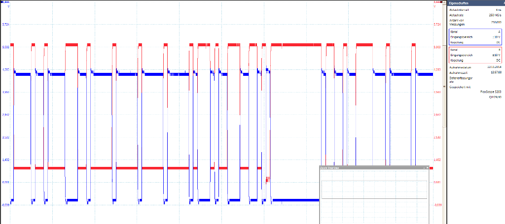
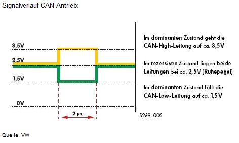
'Using the OBD2 diagnostic port, I'm measuring a high-speed CAN signal (500 kbit/s) with an oscilloscope and connected VCDS, as shown in the pictures. I can also log these CAN commands using KCanMonitor (bitrate 500 kbit/s).'
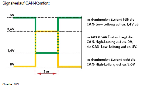
To read the CAN data comfortably, I tapped into the radio connector and, according to my oscilloscope, I'm getting the correct values here (see pictures). However, I'm not getting any logging with the KCanMonitor, neither at 100 kBit, which should be the correct speed, nor at other bitrates.
What am I doing wrong? The attached signals should be correct, and the CAN High and Low connections are also correctly connected (not reversed)?
| Description: |
| Can Komfort - Oszi Messung |
|
| File size: |
69.02 KB |
| Viewed: |
6901 times |
|
| Description: |
|
| File size: |
42.08 KB |
| Viewed: |
5872 times |
|
| Description: |
|
| File size: |
36.71 KB |
| Viewed: |
5694 times |
|
| Description: |
| Diagnose CAN - Oszi Messung |
|

Download |
| File name: |
Diagnose_CAN.pdf |
| File size: |
35.93 KB |
| Downloaded: |
1031 times |
Translated on 04-08-2026, 19:38.
|
|
| Back to top |
|
 |
CAN-Diagnose
Administrator

Joined: 06/07/2011
Posts: 573
Karma: +29 / -0 
Location: Ländle
|
| 25-11-2014, 12:00 Subject: CAN Bus Sniffer: VW Comfort CAN Analysis |
Quote |
|
Hello,
The oscilloscope images look okay, please check if you are connected to the correct pins on the RKS+CAN interface.
The following should be included:
- CAN-H
- CAN-L
- Mass
Best regards, Rainer.
Translated on 04-08-2026, 19:40.
|
|
| Back to top |
Profile PM WWW |
|
Monty
Guest
Free account, no CAN development support
|
| 25-11-2014, 21:06 Subject: CAN Bus Sniffer: VW Comfort CAN Analysis |
Quote |
|
Hello Rainer,
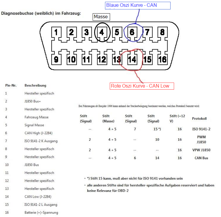
Attached is a picture of my female diagnostic connector and also a diagram showing how the oscilloscope curve was measured at the connector. I suspect that I have selected an incorrect setting in the KCanMonitor software, but I haven't been able to find the correct setting through trial and error.
According to the theory, I would select 100 kbit, and it should work.
Best regards, Ben.
| Description: |
| Messung am OBD2 Female Stecker, der ans Radio angeschlossen ist - Skizze |
|
| File size: |
251.1 KB |
| Viewed: |
14324 times |
|
Translated on 04-08-2026, 19:41.
|
|
| Back to top |
|
|
CAN-Diagnose
Administrator
Joined: 06/07/2011
Posts: 573
Karma: +29 / -0
Location: Ländle
|
| 25-11-2014, 22:09 Subject: CAN Bus Sniffer: VW Comfort CAN Analysis |
Quote |
|
Hello,
Everything looks good, the bitrate should be around 100 kbit/s. You can also measure it using an oscilloscope.
Measure the narrowest width of a level transition and then calculate the bitrate as 1/duration.
The RKS+CAN module terminates the CAN bus with 120 ohms between CAN-H and CAN-L, and each line is connected to ground with 60 ohms. Try removing the ground connection.
Best regards, Rainer.
Translated on 04-08-2026, 19:42.
|
|
| Back to top |
Profile PM WWW |
|
CAN-Diagnose
Administrator
Joined: 06/07/2011
Posts: 573
Karma: +29 / -0
Location: Ländle
|
| 26-11-2014, 19:29 Subject: CAN Bus Sniffer: VW Comfort CAN Analysis |
Quote |
|
Have you ever tried connecting only the CAN-High and CAN-Low lines to the interface?
Okay, please omit the ground connection.
Best regards, Rainer.
Translated on 04-08-2026, 19:43.
|
|
| Back to top |
Profile PM WWW |
|
Monty
Guest
Free account, no CAN development support
|
| 28-11-2014, 15:19 Subject: CAN Bus Sniffer: VW Comfort CAN Analysis |
Quote |
|
Hello Rainer,
Okay, so I've only removed mass and then tried connecting it to both +12V (using just CAN High and CAN Low). Unfortunately, nothing worked, and even swapping the High and Low connections didn't help, which according to my measurements shouldn't be necessary anyway.
The light on the adapter is flashing (red and green) immediately, just like when it's connected to the OBD2 port and receiving CAN messages there.
So, how do I proceed from here? Shouldn't the different signal patterns from the powertrain CAN bus at the OBD2 connector and the comfort CAN bus at the radio pose no problems for the adapter?
Best regards!
Translated on 04-08-2026, 19:44.
|
|
| Back to top |
|
|
Monty
Guest
Free account, no CAN development support
|
| 30-11-2014, 12:07 Subject: CAN Bus Sniffer: VW Comfort CAN Analysis |
Quote |
|
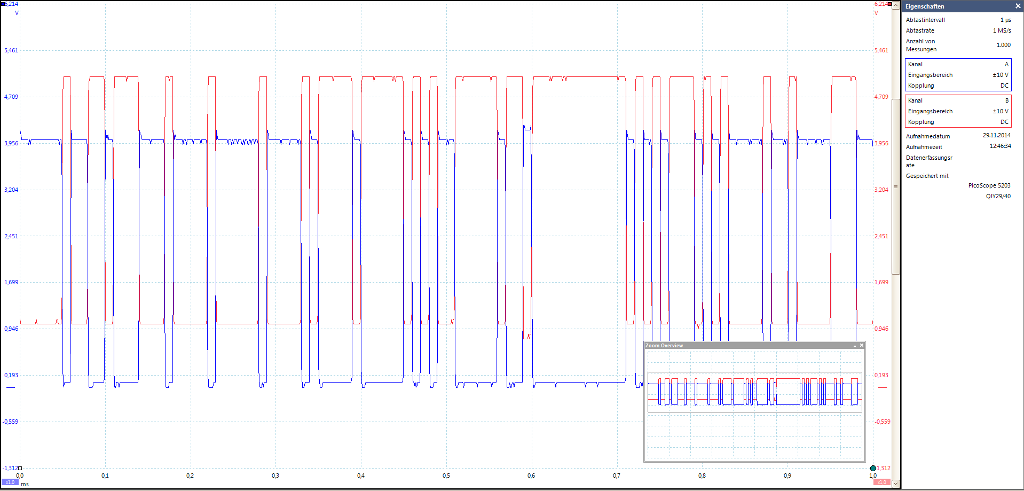
Here's another measurement; you can clearly see that within a one-millisecond time window, the signal changes 100 times, indicating a data rate of 100 kbit, which corresponds to the Comfort CAN signal as described above.
Since I'm currently writing my own program for this, is there a possibility of getting a debug version of the driver, or being able to debug it myself? Otherwise, I'm running out of ideas, and I suspect that the problem might be related to the adapter or the driver.
| Description: |
| Oszi Bild Komfort-CAN 100kBit/s |
|
| File size: |
77.65 KB |
| Viewed: |
2062 times |
|
Translated on 04-08-2026, 19:46.
|
|
| Back to top |
|
|
CAN-Diagnose
Administrator
Joined: 06/07/2011
Posts: 573
Karma: +29 / -0
Location: Ländle
|
| 30-11-2014, 12:58 Subject: CAN Bus Sniffer: VW Comfort CAN Analysis |
Quote |
|
Hi Monty,
It definitely isn't the PC driver causing this; it doesn't care about the bitrate at all.
For testing purposes, you can also bypass the driver DLL and access the virtual serial port directly.
The main difference from the driver DLL is that this DLL provides a programming interface, eliminating the need to repeatedly create functions for parsing and assembling commands.
Did you take the picture of the oscilloscope signal with the hardware connected or without it? It's just that the problem might be related to bus termination or bus topology in the vehicle.
I am currently trying to understand the problem.
Best regards, Rainer.
Translated on 04-08-2026, 19:47.
|
|
| Back to top |
Profile PM WWW |
|
CAN-Diagnose
Administrator
Joined: 06/07/2011
Posts: 573
Karma: +29 / -0
Location: Ländle
|
| 30-11-2014, 13:35 Subject: Low-Speed CAN with RKS+CAN Interface. |
Quote |
|
Hello,
The following has emerged:
- It works (hooray), but...
- The intended (standard) bus timing is for high-speed CAN.
Based on your beautiful oscilloscope images, I assume that all of them were taken without a connected interface.
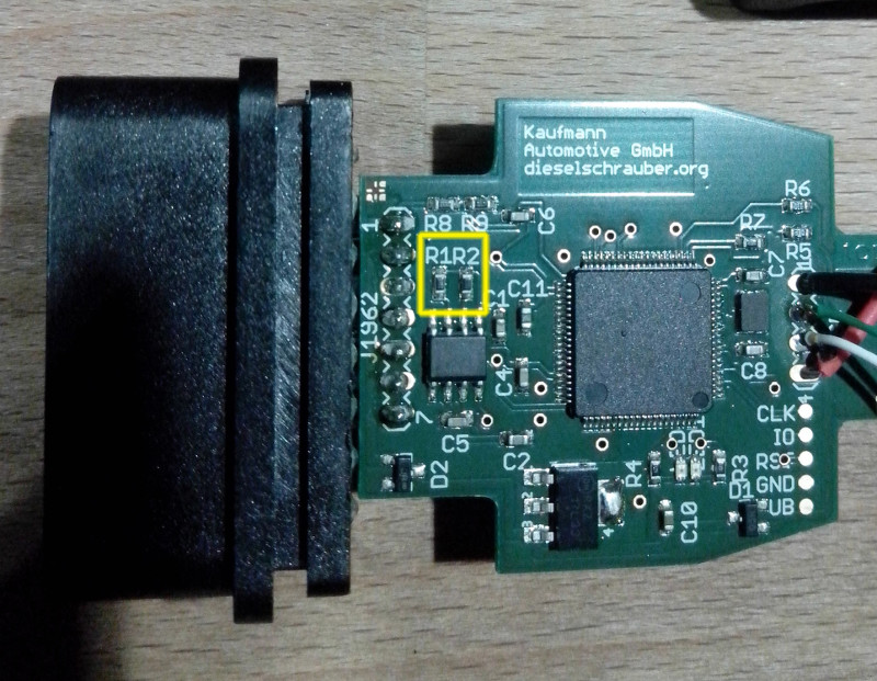
On the RKS+CAN board, you will find two 60-ohm resistors, labeled R1 and R2. These can be "stood up," meaning tilted vertically, so that they can be connected or disconnected as needed.
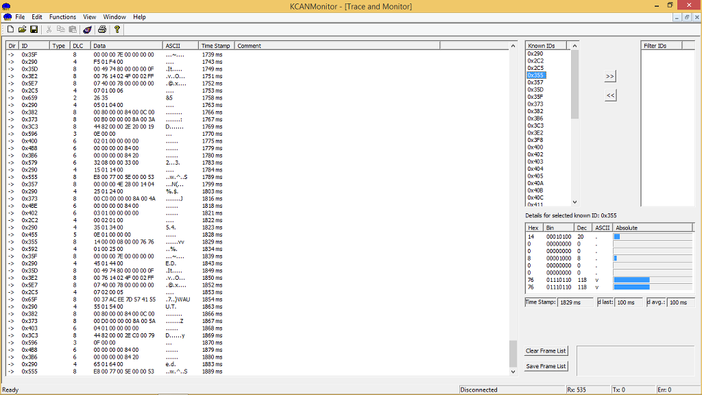
Attached is a log from the Audi A6 4F Comfort CAN bus system.
Here's another tip, since many messages are appearing: If you select entries in the "Known IDs" list and move them to the "Filter IDs" list using the "<<" and ">>" buttons, only those selected entries will be displayed in the log.
If the "Filter IDs" list is empty, all messages will be displayed.
You can find details about each current CAN message by selecting the CAN ID in the "Known-IDs" section.
Best regards, Rainer.
| Description: |
| RKS+CAN an Low-Speed CAN-Komfort (100kBit/s). |
|
| File size: |
245.49 KB |
| Viewed: |
2048 times |
|
| Description: |
| Logdatei CAN-Komfort audi A6 4F. |
|
Download |
| File name: |
Low-Speed-CAN-100kBits.txt |
| File size: |
32.61 KB |
| Downloaded: |
657 times |
Translated on 04-08-2026, 19:50.
|
|
| Back to top |
Profile PM WWW |
|
Monty
Guest
Free account, no CAN development support
|
| 30-11-2014, 21:45 Subject: CAN Bus Sniffer: VW Comfort CAN Analysis |
Quote |
|
Hello Rainer,
Thank you for the effort; that should help me. It's just unfortunate that I have to tinker with the interface, which is why I also have another question about safety: I need to desolder and reposition the resistors marked in yellow on one side (or I could ask a friend who knows about this kind of thing, and hopefully get them to install a switch for it, if possible...). Have I understood that correctly?
Is there a way to intercept the signal externally, by adding resistors outside of the connector (after they are placed on the board), so that I don't have to desolder and resolder everything every time?
Unfortunately, I'm not very knowledgeable about that technically  .
| Description: |
| CAN Bus Sniffer: VW Comfort CAN Analysis |
|
| File size: |
164.35 KB |
| Viewed: |
2278 times |
|
Translated on 04-08-2026, 19:52.
|
|
| Back to top |
|
|
CAN-Diagnose
Administrator
Joined: 06/07/2011
Posts: 573
Karma: +29 / -0
Location: Ländle
|
| 30-11-2014, 22:32 Subject: CAN Bus Sniffer: VW Comfort CAN Analysis |
Quote |
|
Hello Monty,
Yes, that's correct. In your case (i.e., using it with "tapped" CAN lines in the vehicle), you could also omit the resistors.
If scheduling is necessary for other applications, it can also be done externally.
Best regards, Rainer.
Translated on 04-08-2026, 19:54.
|
|
| Back to top |
Profile PM WWW |
|
|


 Bookmarks
 Garage
 FAQ, Legal Notice & Privacy
 RSS Feed
 Register
 Login
Login

