| Author |
Message |
CAN-Diagnose
Administrator

Joined: 06/07/2011
Posts: 575
Karma: +29 / -0 
Location: Ländle
|
 27-05-2016, 20:53 Subject: 27-05-2016, 20:53 Subject: |
Quote |
|
Hello,
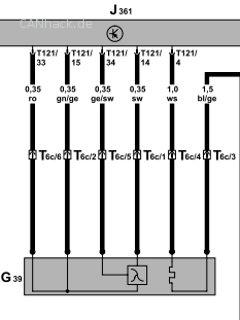
Do you have a picture of the connector socket on the Simos 3 engine control unit?
I'm not sure if this is the right thing to do.
Sure, here's the translation:
"LG" translates to "Best regards" or "Sincerely" in English.
| Description: |
|
| File size: |
11.77 KB |
| Viewed: |
2189 times |
|
Last edited on 27-05-2016, 21:31, edited 1 time in total.
|
|
| Back to top |
Profile PM WWW |
 |
wernernue
Joined: 03/02/2016
Posts: 27
Karma: +10 / -0
Location: Nürnberg
Premium Support
|
| 28-05-2016, 8:48 Subject: |
Quote |
|
CAN-Diagnose wrote: | Hello,
Do you have a picture of the connector socket on the Simos 3 engine control unit?
I'm not sure if this is the right thing to do.
Sincerely |
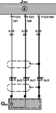
Hello, yes, I have a schematic. I also discovered an error regarding where the GRA pin should be connected. I have a few different versions, but everyone agrees that the knock sensor connects between pins 101 and 109, and the display connects to pin 102 via the cable. That's why I suspect that the text from the error message is incorrect.
But since we're already talking about the broadband probe, that's the next "tough nut to crack," and I have no idea how to simulate it.
It's now measuring the current at pin 14 until the voltage changes at pin 34.
And the behavior changes depending on the load.
I will probably have to live with the error  .
Translated on 03-07-2026, 15:19.
|
|
| Back to top |
Profile PM |
|
CAN-Diagnose
Administrator
Joined: 06/07/2011
Posts: 575
Karma: +29 / -0
Location: Ländle
|
| 29-05-2016, 10:57 Subject: |
Quote |
|
"As is, where is..." or "Without warranty..."
| Description: |
| Anschluß Klopfsensor an Simos 3 |
|
| File size: |
11.89 KB |
| Viewed: |
2076 times |
|
|
|
| Back to top |
Profile PM WWW |
|
wernernue
Joined: 03/02/2016
Posts: 27
Karma: +10 / -0
Location: Nürnberg
Premium Support
|
| 29-05-2016, 16:02 Subject: |
Quote |
|
CAN-Diagnose wrote: | | No warranty... |
Thank you, Rainer, for your efforts.
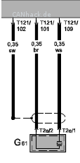
At least the pins to which the crystal is connected are the same. I'll try to apply some kind of signal that is similar to the original. If the pins are correct, then a different error message might appear.
According to my records, the shield is connected to pin 102.
| Description: |
|
| File size: |
5.24 KB |
| Viewed: |
1747 times |
|
Translated on 03-07-2026, 15:19.
|
|
| Back to top |
Profile PM |
|
wernernue
Joined: 03/02/2016
Posts: 27
Karma: +10 / -0
Location: Nürnberg
Premium Support
CAN-Diagnose likes this. |
| 12-07-2016, 20:37 Subject: CAN message for MIL and EPC lamp |
Quote |
|
Here's a small addition again.
A very interesting address is 0x480.
Bytes 2 and 3 are used to transmit the consumption data to the AI. Someone in this forum has already figured that out.
However, byte 1 contains the information for the MIL (Malfunction Indicator Lamp, also known as the check engine light) and the EPC (Electronic Power Control) lamp, which illuminates when the accelerator pedal or throttle valve provides implausible signals.
The third bit from the right is 1 when the EPC lamp is activated, and the fourth bit is... The rightmost bit is 1 when the MIL is enabled.
Using an AND operation, you can then set the two variables for the two lamps.
The consumption calculation measures the difference in consumed microliters every second. This difference is then multiplied by 3600 and divided by 10000, because the display shows the consumption in liters with two decimal places. The decimal point is permanently enabled for this function.
Here is the Arduino code for selecting the MIL and EPC lamps, as well as for calculating power consumption.
Code: |
if (rxId==0x480)
{
Byte_0x480_1 = rxBuf[1]; //MIL und EPC
Byte_0x480_2 = rxBuf[2]; //Verbrauch_LB
Byte_0x480_3 = rxBuf[3]; //Verbrauch_HB
MIL = Byte_0x480_1 & B00001000;
if (MIL > 0) {digitalWrite(MIL_PIN,HIGH);} else {digitalWrite(MIL_PIN,LOW);}
EPC = Byte_0x480_1 & B00000100;
if (EPC > 0) {digitalWrite(EPC_PIN,HIGH);} else {digitalWrite(EPC_PIN,LOW);}
//Verbrauchsberechnung
CurrentVB = Byte_0x480_2 + (Byte_0x480_3 & B01111111)*256;
if (currentMillis - previousMillis >= interval)
{
previousMillis = currentMillis;
if (CurrentVB<LastVB) {VB=CurrentVB+0x8000-LastVB;} else {VB=CurrentVB-LastVB;}
VBh = VB*0.36;
LastVB = CurrentVB;
}
} |
Translated on 03-07-2026, 15:19.
|
|
| Back to top |
Profile PM |
|
wernernue
Joined: 03/02/2016
Posts: 27
Karma: +10 / -0
Location: Nürnberg
Premium Support
|
| 04-02-2017, 0:11 Subject: Can ID speed signal from the ABS control unit |
Quote |
|
Hello, I have a question.
I want to send the speed signal from my simulation to the instrument cluster (IC) via CAN. Currently, I'm doing this by sending a rectangular signal to the corresponding pin on the IC. However, I had to rewire the connection in the plug on the instrument cluster, so I'm sure the instrument cluster was definitely being controlled via CAN.
I suspect that the ABS control unit sends the signal to the instrument cluster via the drive bus.
However, the ID 0x351, which I found mentioned in several posts, is not working.
Does anyone have an idea what ID the AI needs to display the speed signal?
Best regards,
Werner.
Translated on 03-07-2026, 15:19.
|
|
| Back to top |
Profile PM |
|
wernernue
Joined: 03/02/2016
Posts: 27
Karma: +10 / -0
Location: Nürnberg
Premium Support
CAN-Diagnose likes this. |
| 07-02-2017, 0:28 Subject: Speed information in the CAN bus |
Quote |
|
I found an interesting article that also contains the solution to my question.
Two CAN messages need to be sent.
Address 0x5A0: 0xFF, speedL, speedH, 0xB0, 0x00, 0x00, 0x00, 0xAD
Address 0x1A0: 0x18, speedL, speedH, 0x00, 0xFE, 0xFE, 0x00, 0xFF
Here's another link to the article:
https://hackaday.io/project/6288-volkswagen-can-bus-gaming
Translated on 03-07-2026, 15:19.
|
|
| Back to top |
Profile PM |
|
wernernue
Joined: 03/02/2016
Posts: 27
Karma: +10 / -0
Location: Nürnberg
Premium Support
CAN-Diagnose and majonez likes this. |
| 14-04-2017, 20:09 Subject: Polo On-Board Computer |
Quote |
|
Hello everyone,
Here's a small update on my Arduino project.
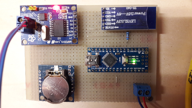
I currently have two onboard computers running. One is connected to my virtual polo (as described at the beginning), and since it's built on a breadboard, it's a fairly compact solution that can also be easily installed in a vehicle.
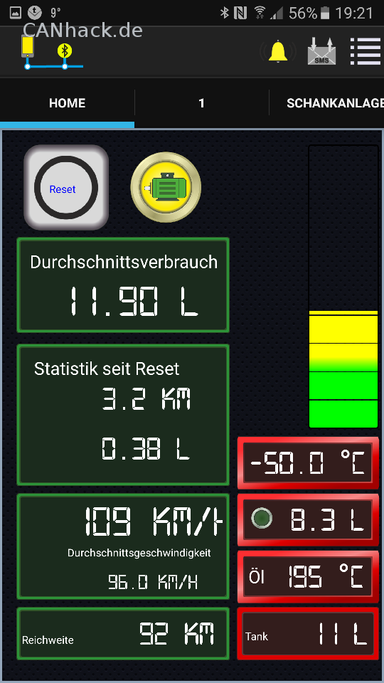
The sensor data is transmitted via a Bluetooth module to an Android phone or tablet. The "Virtuino" app is used for display purposes. With its freely configurable interface, you can create a visually appealing page that displays all the retrieved values simultaneously. The values displayed on the screen are updated every 500 milliseconds.
The following values are read from the CAN bus:
- Cruise control status.
- Fuel tank capacity
- Outdoor temperature
- Oil temperature
- Turn on the light.
- Speed
- Distance
- MIL and EPC (if required as a tax output for the control lamp).
- Consumption
Here is the code for evaluating the corresponding bytes.
Code: |
if (rxId==0x288) //0x288 Tempomat ein
{
Byte_0x288_2=rxBuf[2];
TempomatEin=Byte_0x288_2 & B01000000; //Status Tempomat aktiv
}
if (rxId==0x320)
{
Byte_0x320_2=rxBuf[2];
Tankinhalt=Byte_0x320_2; //Tankinhalt in Liter
}
if (rxId==0x420) //0x420 Außentemperatur vom KI 421 vom Tester
{
Byte_0x420_2=rxBuf[2]; //Außentemperatur
Byte_0x420_3=rxBuf[3]; //Öltemperatur
Byte_0x420_5=rxBuf[5]; //Licht ein
Licht=Byte_0x420_5 & B01010000;
ATmp=10*(Byte_0x420_2-100)/2;
oelt=Byte_0x420_3-60;
}
if (rxId==0x5A0) //0x5A0 Geschwindigkeit vom ABS
{
Byte_0x5A0_1=rxBuf[1]; //Geschwindigkeit LB
Byte_0x5A0_2=rxBuf[2]; //Geschwindigkeit HB
Byte_0x5A0_5=rxBuf[5]; //Wegstrecke LB
Byte_0x5A0_6=rxBuf[6]; //Wegstrecke HB
Kmh=(Byte_0x5A0_2*254+Byte_0x5A0_1)/152;
CurrentStrecke=Byte_0x5A0_5 + (Byte_0x5A0_6 & B00000111)*256;
}
if (rxId==0x480) //0x480 Verbrauch vom MSG, Berechnung in ml
{
Byte_0x480_1=rxBuf[1]; //MIL&EPC
Byte_0x480_2=rxBuf[2]; //Verbrauch_LB
Byte_0x480_3=rxBuf[3]; //Verbrauch_HB
MIL=Byte_0x480_1 & B00001000;
if ( MIL == 8 ) {digitalWrite(MIL_PIN,HIGH);} else {digitalWrite(MIL_PIN,LOW);}
EPC=Byte_0x480_1 & B00000100;
if ( EPC == 4 ) {digitalWrite(EPC_PIN,HIGH);} else {digitalWrite(EPC_PIN,LOW);}
CurrentVB=Byte_0x480_2 + (Byte_0x480_3 & B01111111)*256;
}
|
Please provide the German text you would like me to translate into English.
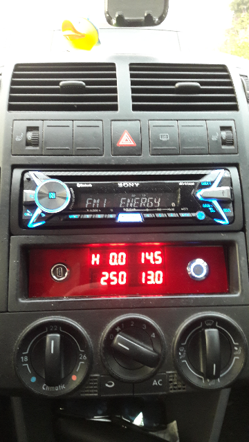
A second on-board computer is installed in the real Polo, but in this case, it features a 7-segment display. Controlling the display requires significantly more complex code, but it has the advantage of not requiring a smartphone.
On the RTC module, the values for fuel consumption, distance traveled, driving time, and display mode are saved every 10 seconds and reloaded when the ignition is turned on.
You can see what it looks like in the pictures.
Happy Easter to all CAN-Hackers.
Werner.
| Description: |
Hier der Aufbau des Bordcomputers für die Anzeige mit der Virtuino App.
Oben links ist das CAN-Modul zu sehen, oben rechts das Bluetooth Modul,
unten links die RTC zum Speichern der Werte und unten rechts der Arduino Nano.
Angeschlossen wird nur die Betriebsspannung und der CAN-Bus. |
|
| File size: |
536.57 KB |
| Viewed: |
1338 times |
|
| Description: |
Ansicht des Virtuino-Displays.
Die gelbe Lampe mit dem Motorsymbol zeigt den aktiven Tempomat an.
Die Anzeige des aktiven Tempomat fehlt ja meist bei Nachrüstung.
Außerdem wird hier die Außentemperatur vom KI nicht gesendet, deshalb zeigt die Anzeige -50° an. Die angezeigten Werte sind von dem "virtuellen Polo" |
|
| File size: |
125.26 KB |
| Viewed: |
1280 times |
|
| Description: |
Hier der eingebaute Bordcomputer im Polo.
Angezeigt wird oben links der aktuelle Spritverbrauch, (H=liter/h bei Geschwindigkeit unter 10km/h), oben rechts die Außentemperatur, unten links die verbleibende Reichweite, errechnet aus Tankinhalt/Durchschnittsverbrauch, und unten rechts der Tankinhalt in Liter. |
|
| File size: |
455.75 KB |
| Viewed: |
1188 times |
|
Translated on 03-07-2026, 15:19.
|
|
| Back to top |
Profile PM |
|
Clubsport
Joined: 01/20/2017
Posts: 4
Karma: +0 / -0
Free account, no CAN development support
|
| 25-04-2017, 7:21 Subject: |
Quote |
|
Very cool work!!! 
Translated on 03-07-2026, 15:19.
|
|
| Back to top |
Profile PM |
|
wernernue
Joined: 03/02/2016
Posts: 27
Karma: +10 / -0
Location: Nürnberg
Premium Support
|
| 25-04-2017, 23:48 Subject: Onboard computer |
Quote |
|
Thank you 
The on-board computer is paying for itself now, because my son is driving more fuel-efficiently.
And the outside temperature provides an added safety margin when it gets frosty again.
Translated on 03-07-2026, 15:19.
|
|
| Back to top |
Profile PM |
|
Dr4g0n
Joined: 06/10/2017
Posts: 4
Karma: +0 / -0
Free account, no CAN development support
|
| 11-06-2017, 19:22 Subject: |
Quote |
|
Hi, where did you connect to the CAN bus? I'm connected to the radio connector and can't find some of the values. I have a Polo 9n3 without MFA. I'm using an MCP2515 with 8MHz and a speed of 100kbps for reading. Is the problem already somewhere there, or are there no outside temperature readings, etc., for me? I can read the engine speed. Thank you very much.
Translated on 03-07-2026, 15:19.
|
|
| Back to top |
Profile PM |
|
wernernue
Joined: 03/02/2016
Posts: 27
Karma: +10 / -0
Location: Nürnberg
Premium Support
|
| 12-06-2017, 8:12 Subject: |
Quote |
|
Hello,
I'm connected to the vehicle's drive CAN bus at the speedometer with a data rate of 500 kbps.
"I'm also using the MCP2515 with an 8MHz clock and a library where you can specify the clock rate." But if you can read values, then it should work.
Unfortunately, I cannot specify which values are transmitted through the CAN gateway to the comfort bus (at the radio) and which are not.
Currently, I have only wired the drive control bus in my test setup.
Regards,
Werner.
Translated on 03-07-2026, 15:19.
|
|
| Back to top |
Profile PM |
|
CAN-Diagnose
Administrator
Joined: 06/07/2011
Posts: 575
Karma: +29 / -0
Location: Ländle
|
| 12-06-2017, 11:15 Subject: |
Quote |
|
Not all CAN messages are available on every CAN bus. 
It doesn't really make sense if the engine control unit were told which button was pressed on the radio. 
Best regards, Rainer. |
|
| Back to top |
Profile PM WWW |
|
Dr4g0n
Joined: 06/10/2017
Posts: 4
Karma: +0 / -0
Free account, no CAN development support
|
| 12-06-2017, 20:28 Subject: |
Quote |
|
Thank you very much.
I've wired everything up, and it's working perfectly.
I was aware that not everything is available to everyone.
Now it makes sense that the speed setting on the comfort bus is used to control the radio volume.
Is there a list available somewhere that details the data accessible via the CAN bus?
I am missing the following in the examples:
Speed (regarding comfort, engine load, turbo boost, oil pressure, etc.).
I have noticed two inconsistencies in the code examples.
1. ATmp of Value * 10
2. When the "On" position is selected, the light output is 16.
Translated on 03-07-2026, 15:19.
|
|
| Back to top |
Profile PM |
|
irobles
Joined: 06/13/2017
Posts: 3
Karma: +0 / -0
Free account, no CAN development support
|
| 14-06-2017, 11:29 Subject: |
Quote |
|
Hello, sorry but I don't speak German  .
"I've started a new R&D project on CAN-BUS security, and I'd like to install a similar panel as the one shown in your photos. I understand you used equipment from a VW Polo. If it's not too much trouble, could you please provide the reference numbers for the ECUs and the speedometer?" I'm trying to find a full set on the Internet, but it's a nightmare  .
Thank you very much for your time.
Best regards,
Igor.
Translated on 03-07-2026, 15:19.
|
|
| Back to top |
Profile PM |
|
Dr4g0n
Joined: 06/10/2017
Posts: 4
Karma: +0 / -0
Free account, no CAN development support
|
| 10-07-2017, 20:29 Subject: |
Quote |
|
My onboard computer is working properly now.
However, I'm in a bit of a "strange" situation.
The distance will be calculated using your formula, but what is that value?
It looks like the CM (presumably referring to a counter or memory) is being decremented, but the value resets to approximately 2048 each time.
Do you have any ideas about this?
Translated on 03-07-2026, 15:19.
|
|
| Back to top |
Profile PM |
|
|


 Bookmarks
 Garage
 FAQ, Legal Notice & Privacy
 RSS Feed
 Register
 Login
Login
