| Author |
Message |
mulltor
Guest
Free account, no CAN development support
|
|
| Back to top |
|
 |
CAN-Diagnose
Administrator

Joined: 06/07/2011
Posts: 575
Karma: +29 / -0 
Location: Ländle
|
 13-08-2011, 22:59 Subject: CAN Signal Analysis: Oscilloscope Screenshots 13-08-2011, 22:59 Subject: CAN Signal Analysis: Oscilloscope Screenshots |
Quote |
|
Hello,
wo gemessen, evtl. einfach die falschen Kabel angezapft? What bitrate?
Remove the GND wire from the CAN cable harness; otherwise, I don't need anything else, just more information from you.
Best regards, Rainer.
Last edited on 13-08-2011, 23:00, edited 1 time in total.
|
|
| Back to top |
Profile PM WWW |
|
mulltor
Guest
Free account, no CAN development support
|
| 14-08-2011, 9:23 Subject: CAN Signal Analysis: Oscilloscope Screenshots |
Quote |
|
Hello Rainer,
Thank you for your reply.
Measured relative to the X30/4 CAN-B connector in the vehicle (see attachment).
Bitrate: 83 kbit/s (Attachment) = BRGCON register: Hex 09BE07 (via MBTime).
GND disconnected / Protective earth connected to the chassis.
The can tool monitor remains silent.
Best regards,
Volker
| Description: |
| screenshot Umrechnung 83kBits-->BRGCON-Register |
|

Download |
| File name: |
BitTime 83kBits.pdf |
| File size: |
144.4 KB |
| Downloaded: |
984 times |
Translated on 08-08-2026, 15:52.
|
|
| Back to top |
|
|
CAN-Diagnose
Administrator
Joined: 06/07/2011
Posts: 575
Karma: +29 / -0
Location: Ländle
|
| 14-08-2011, 14:54 Subject: CAN Signal Analysis: Oscilloscope Screenshots |
Quote |
|
Hello,
It's commendable to provide the source for the PDFs, but that doesn't automatically grant the right to distribute the files on the web. Therefore, I have removed them.
Has the interaction between the CAN interface and software already worked with a standard communication rate, such as 500 kbit/s?
Best regards, Rainer.
Last edited on 01-12-2014, 19:58, edited 4 times in total.
|
|
| Back to top |
Profile PM WWW |
|
mulltor
Guest
Free account, no CAN development support
|
| 14-08-2011, 20:48 Subject: CAN Signal Analysis: Oscilloscope Screenshots |
Quote |
|
Hello CAN Hacker,
Sorry about the files I uploaded – I didn't realize that could cause problems.
'Trying standard communication methods like 500 kbit/s provided some useful information.' - 'I just connected the can tool/USB adapter to the engine bus, but unfortunately, that didn't work either.'
The engine bus produces a decent signal on the oscilloscope (see attachment): 500 kbit/s - although it's still just a weak signal of only about 1.0 volts, but otherwise, it looks like a CAN signal.
On the oscilloscope, the Comfort Bus also showed the correct data rate of 83 kbit/s. (see above)
It seems that the vehicle's bit rate and the settings of the can tool are already compatible.
Okay, now I really need a good idea of what the can tool/USB adapter might be missing...
So far tested:
- Resistance between my test clip's low and high terminals: 66 ohms - OK.
- Short circuit between ground/signal lines/shield: negative - everything is fine.
Is there any other test that could help me troubleshoot this issue? Can I somehow verify the output from the CANUSB device? I want to make sure that the CANUSB is functioning correctly and that data is actually being received by the can tool.
Best regards,
Volker
| Description: |
| Oszi-screenshot vom 500 kbits-Signal aus dem KfZ |
|
Download |
| File name: |
Engine 2.pdf |
| File size: |
111.72 KB |
| Downloaded: |
886 times |
Translated on 08-08-2026, 15:56.
|
|
| Back to top |
|
|
CAN-Diagnose
Administrator
Joined: 06/07/2011
Posts: 575
Karma: +29 / -0
Location: Ländle
|
| 14-08-2011, 21:43 Subject: CAN Signal Analysis: Oscilloscope Screenshots |
Quote |
|
Check the pin assignments on the CAN adapter and try swapping the CAN_L and CAN_H pins.
I had specifically marked the corresponding lines on my car with labeled tape, and then I mistakenly put the "L/H" label on incorrectly. 
Best regards, Rainer. |
|
| Back to top |
Profile PM WWW |
|
mulltor
Guest
Free account, no CAN development support
|
| 15-08-2011, 12:18 Subject: CAN Signal Analysis: Oscilloscope Screenshots |
Quote |
|
Hello,
Thanks for the tip – it would have been great, but unfortunately, that didn't work out either.
For testing purposes, I swapped pins 2 and 7 on the CAN bus adapter - still no activity on the CAN Hacker monitor.
Best regards,
Volker
Translated on 08-08-2026, 15:59.
|
|
| Back to top |
|
|
Dieselfahrer
CAN-Profi

Joined: 07/28/2011
Posts: 79
Karma: +6 / -0
CAN Support
|
| 15-08-2011, 22:49 Subject: CAN Signal Analysis: Oscilloscope Screenshots |
Quote |
|
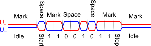
The readings you measured don't look right to me.
Could you please check the grounding? It seems to be an issue, especially on the CAN-High line, as if the ground reference is drifting.
CAN essentially functions like RS-485, so the signals should appear to be bidirectional.
I'm not familiar with your adapter; what bus driver does it use?
Could you please check the RX line on the TTL side to see if anything is actually arriving there?
| Description: |
| CAN Signal Analysis: Oscilloscope Screenshots |
|
| File size: |
7.49 KB |
| Viewed: |
1958 times |
|
Translated on 08-08-2026, 16:00.
|
|
| Back to top |
Profile PM |
|
mulltor
Guest
Free account, no CAN development support
|
| 21-08-2011, 11:18 Subject: CAN Signal Analysis: Oscilloscope Screenshots |
Quote |
|
Thank you for the tips – unfortunately, I'm still not getting any signal on the can tool monitor.
The levels you measured don't look okay to me.
Could you please check the mass (it seems to be especially noticeable on the CAN-High line, as if the zero line is drifting).
Resistance is okay - measured: 0 Ohms.
'However, the baseline is now fluctuating wildly up and down (see attachments) – it was much more stable on August 13th... I have no idea what's going on. Could this be a problem for the TTL?'
CAN essentially functions like RS-485, therefore the signals should appear to be bidirectional.
I only have a single-channel oscilloscope and I recorded each channel separately. Therefore, the complementary signal is missing from my screenshots.
I don't know your adapter, what bus driver does it use?
LAWICEL-CANUSB Adapter - http://www.canusb.com/
Driver: FTDI version 2.8.12.0.
Alternative tried: VCP driver.
More information about the drivers can be found at: http://www.canusb.com/downloads.htm
Could you please measure on the RX side of the TTL interface to see if anything is actually arriving there?
I'm afraid I can't do that right now - the LAWICEL adapter is a small SMD component (attachment), and the RX pin isn't labeled. If someone can tell me where to put the probe, I might be able to take some measurements.
Best regards,
Volker
| Description: |
|
Download |
| File name: |
unten.JPG |
| File size: |
2.39 MB |
| Downloaded: |
3725 times |
| Description: |
|
Download |
| File name: |
oben.JPG |
| File size: |
1.99 MB |
| Downloaded: |
827 times |
| Description: |
| Masse o.k. - Nulllinie bergauf/bergab |
|
Download |
| File name: |
CAN_High_83kBit.pdf |
| File size: |
36.01 KB |
| Downloaded: |
620 times |
| Description: |
| Masse o.k. - Nulllinie bergauf/bergab |
|
Download |
| File name: |
CAN_Low_83kBit.pdf |
| File size: |
35.38 KB |
| Downloaded: |
636 times |
Translated on 08-08-2026, 16:03.
|
|
| Back to top |
|
|
Dieselfahrer
CAN-Profi
Joined: 07/28/2011
Posts: 79
Karma: +6 / -0
CAN Support
|
| 21-08-2011, 19:53 Subject: CAN Signal Analysis: Oscilloscope Screenshots |
Quote |
|
Quote: | | Despite this, my baseline is now fluctuating wildly up and down (attachments) - the baseline on August 13th was much better in comparison... I have no idea what's going on. Could this be a problem for the TTL? |
If the signals are really like that, then it definitely won't work.
But: Is the oscilloscope set to measure DC voltage?
What measurements did you take - just from the car to the adapter, or also to the oscilloscope?
Quote: | | I only have a single-channel oscilloscope, and I've recorded only one channel at a time. Therefore, the complementary signal is missing from my screenshots. |
Okay, but your signals still look wrong; the start bit is high in both cases, and that's not possible.
Okay, the bus controller is the 82C251; you can find the datasheet online.
Quote: | Could you please measure on the RX side of the TTL interface to see if anything is actually arriving there?
{Unfortunately}, I can't do that right now - the LAWICEL adapter is a small SMD component (attachment), and the RX pin isn't labeled. {If someone can help me figure out where to place the probe}, I might be able to take some measurements.{
Please provide the text you would like me to translate from German to English. I will then give you only the translation, without any explanations.
Best regards,
Ingo |
Translated on 08-08-2026, 16:07.
|
|
| Back to top |
Profile PM |
|
mulltor
Guest
Free account, no CAN development support
|
| 23-08-2011, 19:05 Subject: CAN Signal Analysis: Oscilloscope Screenshots |
Quote |
|
The zero-line drift is now gone – it was my mistake. I only powered the PC oscilloscope from the battery laptop instead of the mains-powered laptop – thanks for pointing that out!
'...okay, it's not completely gone, but it's better than last time - so it should be okay for the adapter, right?'
The start bits for CANHigh and CANLow are now also running in opposite directions.
'...unfortunately, nothing is arriving at the RX pin of the 82C251 (except for a constant 4.5V) - and now I'm stuck again...'
Unfortunately, I was unable to complete the 'Testing the CANUSB' section from the installation manual.
Section 1.2 in http://www.canusb.com/documents/canusb_manual.pdf.
Has anyone ever tried this before? From which directory in the terminal should I even start? How do I ensure that I have hardware and software handshaking disabled...?
Or am I going down the wrong path again?
The adapter is flashing its self-test sequence three times, indicating 'everything's okay' – what else could possibly be wrong now?
| Description: |
| CAN Signal Analysis: Oscilloscope Screenshots |
|
Download |
| File name: |
CANLow_83kBit_Masse.pdf |
| File size: |
33.71 KB |
| Downloaded: |
689 times |
| Description: |
| CAN Signal Analysis: Oscilloscope Screenshots |
|
Download |
| File name: |
CANHigh_83kBit_Masse.pdf |
| File size: |
34.65 KB |
| Downloaded: |
608 times |
Translated on 08-08-2026, 16:11.
|
|
| Back to top |
|
|
Dieselfahrer
CAN-Profi
Joined: 07/28/2011
Posts: 79
Karma: +6 / -0
CAN Support
|
| 24-08-2011, 17:14 Subject: CAN Signal Analysis: Oscilloscope Screenshots |
Quote |
|
mulltor wrote: | The zero-line drift is now gone - it was my mistake - I only operated the PC oscilloscope using the battery-powered laptop instead of the mains-powered laptop - thank you for pointing that out!
...okay, it's not completely gone, but it's better than last time - it should be okay for the adapter, right? |
No, definitely not. Anything that goes outside the range of 0V and 5V is completely unacceptable.
Please describe the structure again and explain how everything is connected.
Car - CAN adapter - Oscilloscope - Laptop.
Quote: | | The start bits CANHigh and CANLow are now also running in opposite directions. |
That looks better, but it's not enough, see above.
Quote: | | ...unfortunately, nothing is arriving at the RX pin of the 82C251 (except for a constant 4.5V) - now I'm stuck again... |
If your screenshots aren't just measurement errors, I'm not surprised. However, 4.5V is also quite unusual – therefore, see above.
Quote: |
Unfortunately, I was unable to complete the "Testing the CANUSB" section from the installation manual.
Section 1.2 in http://www.canusb.com/documents/canusb_manual.pdf.
Has anyone ever tried this before? What path in the terminal should I even start from? How do I ensure that I have hardware and software handshaking disabled...?
or am I already on the wrong track again? |
If your Windows is in German: In the settings, set the flow control to "disabled" (not hardware, not software).
But I don't think you're at that stage yet, so it probably wouldn't be a problem.
Translated on 08-08-2026, 16:15.
|
|
| Back to top |
Profile PM |
|
mulltor
Guest
Free account, no CAN development support
|
|
| Back to top |
|
|
Dieselfahrer
CAN-Profi
Joined: 07/28/2011
Posts: 79
Karma: +6 / -0
CAN Support
|
| 30-08-2011, 10:48 Subject: CAN Signal Analysis: Oscilloscope Screenshots |
Quote |
|
Quote: | Attachment (attachment)
The chassis was additionally grounded, which finally eliminated the drift.
CANH on the connector is now between 0 and +4 volts (attachment).
CANL on the connector now supports a voltage range of +2V to -2V (attachment).
CANL and CANH at the 82C251, ranging from 0 to 4 volts (see attachment).
|
The CANL and CANH signals on the 82C251 now appear to have correct voltage levels, but we are again experiencing the problem where both signals have a low idle level – this cannot be right. Is this happening twice with the same issue?
(The voltage levels at the connector must be due to measurement errors – after all, there should only be three wires between the connector and the 82C251 chip, and it's impossible for a 2V DC voltage drop to occur across just those three wires.)
Quote: | | Still nothing on the RX except for the steady 4.5 volts with a few peaks (attachment) | .
This perfectly explains why CANL and CANH appear to be the same on the 82C251.
Translated on 08-08-2026, 16:21.
|
|
| Back to top |
Profile PM |
|
mulltor
Guest
Free account, no CAN development support
|
| 31-08-2011, 19:16 Subject: CAN Signal Analysis: Oscilloscope Screenshots |
Quote |
|
Bullseye! / Hit!
While I haven't seen the same signal twice, I'm measuring the same signal on the CANL pin as I am on the CANH pin.
'When I disconnect the connector from the CANH port, I also see a CANL signal on the USB adapter. When I reconnect the connector, my CANL signal disappears, and I have a low-level signal on both the CANL and CANH ports.'
CANL to GND, CANH to GND.
CANL to protective conductor, CANH to protective conductor.
Connect the protective conductor to ground (GND).
...everything's okay.
Could it be that the parallel 2x120 Ohm resistors between CANL and CANH are not sufficient? I'm measuring 60 Ohms between CANL and CANH - shouldn't that actually be the specified value, or what?
'Would it be safe to temporarily solder in two 1 kΩ resistors, or would it be okay to completely remove the resistors without damaging anything?'
Best regards,
Volker
Translated on 08-08-2026, 16:24.
|
|
| Back to top |
|
|
Dieselfahrer
CAN-Profi
Joined: 07/28/2011
Posts: 79
Karma: +6 / -0
CAN Support
|
| 31-08-2011, 22:41 Subject: CAN Signal Analysis: Oscilloscope Screenshots |
Quote |
|
Quote: | Hit!
While I haven't seen the same signal twice, I'm measuring the same signal on the CANL pin as I am on the CANH pin.
If I unplug the connector from the CANH interface, then I also have the CANL signal at the USB adapter. |
Okay, let's slow down: You've unplugged the connector from the CAN interface, the CAN adapter is connected to the computer, and you're measuring directly at the CAN adapter – what exactly are you measuring?
Baseline? Or is there already a signal present?
Quote: | When I plug the connector back in, my CANL signal disappears, and I have a signal with a low resting level on both the CANL and CANH lines.
CANL to GND, CANH to GND.
CANL to protective conductor, CANH to protective conductor.
Connect the protective conductor to ground (GND).
...everything's okay | .
If you've simply plugged the CAN adapter into your computer, it should leave the CAN bus undisturbed. That means the "incorrect" signal is likely coming from the CAN connector itself. Is the pin configuration 100% correct?
Quote: | Could it be that the parallel 2x120 Ohm resistors between CANL and CANH are not sufficient? I am measuring 60 Ohms between CANL and CANH - which should actually be the specified value, or not?
Should I temporarily try soldering in two 1 kΩ resistors or completely remove the resistors without anything breaking? |
Having 120 ohms at the end and measuring 60 ohms is perfectly correct. There's no need to change anything.
Translated on 08-08-2026, 16:27.
|
|
| Back to top |
Profile PM |
|
|


 Bookmarks
 Garage
 FAQ, Legal Notice & Privacy
 RSS Feed
 Register
 Login
Login
